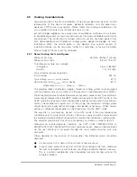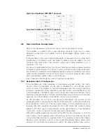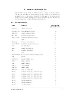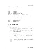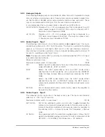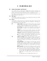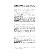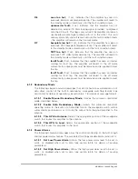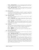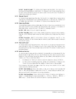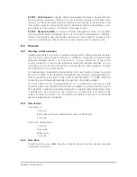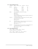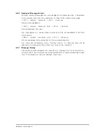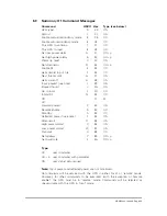
Code
Function
User interface
pin identification
RS RX
7
serial interface Rx
7
e
HX I MON
helix current monitor analogue output
f
ADD 2
address select 2
g
ADD 3
address select 3
h
ADD 4
address select 4
i
ADD 5
address select 5
j
RED FLT O/P
redundancy fault indicator output
k
RED SW 1
redundancy RF switch drive 1 – this HPA to antenna
m
RED SW 2
redundancy RF switch drive 2 – this HPA to load
n
RS GND
serial interface signal return
p
SWITCH SENSE redundancy RF switch sense input
q
AUTO ENA
redundancy automatic mode enable input
r
RED SEL
redundancy select input
s
RED FLT I/P
redundancy fault input
t
5.2
User Interface Features
5.2.1
Indicator Outputs - Type 1
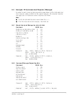
Normally open relay contact outputs switched to GND (pin P on the user interface
connector) when condition is true.
Example 1
amplifier in the OFF mode is indicated by pin A on the user interface
connector closing to pin ’P’.
Example 2
MUX 0 fault line is at binary 1 when pin X on the user interface
connector closes to pin P.
OFF IND
Indicates power is applied and that the unit is in the OFF mode.
WARMUP IND Indicates the TWT cathode three minute warm-up timer is operating
and that the unit is in the WARMUP mode.
STBY IND
Indicates the TWT Cathode warm-up is complete, the unit is in the
STDBY (standby) mode and is ready to enter the XMIT mode.
XMIT IND
Indicates the unit is in the XMIT (transmit) mode.
SUM FLT IND Indicates the unit has detected a fault condition.
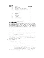
MUX 0
MUX 1
MUX 2
MUX 3
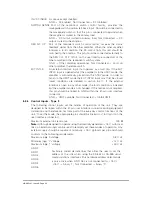
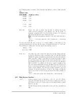
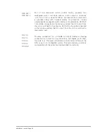
Four binary coded discrete lines that indicate the fault conditions;
the following list gives a breakdown of these fault conditions with a
brief description of reset conditions.
HBN63xx-1, Issue 8, Page 21

