background image


U

SER 

M

ANUAL 


16

K

/8

CXP


M

ONO 


R

EV 

K


06/2017


P

A G E  

|


25 


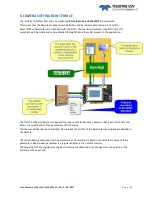
If the single CoaxPress Trigger is used, the Synchronization mode using 2xTriggers can’t be used. 


7.3.1


External Triggers on GPIO Connector 

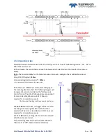
An External GPIO connector allows the camera to used 2 lines for triggering (Line0 and Line1) 
The end-user has the responsibility of the definition of the triggering system. 
The mapping describes all features available to define a trigger system 
 

7.3.2


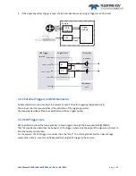
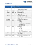
CXP Trigger Line 

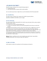
CXP specification allows the frame grabber to send triggers through the low speed link0 (@20MHz) 
The CXP specification describes the behavior of the trigger, where only the edge of the signal and a timer to 
limit the latency is described. 
For the camera, the CXP trigger is consider to be the “line2”. The Frame grabber itself can also manage 
several lines, timers, counter and finally send this single CXP trigger to the camera. 

Trigger 
module 

Line0 

Line1 

Line2 

CXP 
modul

Camera 

GPIO 

modul

IO control 

- Debounce 

- Inverter 

- rescaler  

Logical Unit 

Line0 

Line1 

≥1 

Line0 

Line1 

Line0 

 Line1 

Line0 + Line1 

HW Trigger 
source 

CXP module 

Line2 

Line2 

Содержание ELIIXA+ 16K/8K CXP MONO

Страница 1: ...ELIIXA Family CMOS Multi Line Camera e2v com cameras USER MANUAL ELIIXA 16K 8K CXP MONOCHROME...

Страница 2: ...ciency 9 2 4 2 Spectral Response 9 3 CAMERA HARDWARE INTERFACE 11 3 1 Mechanical Drawings 11 3 2 Input output Connectors and LED 12 3 2 1 Power Over CoaXPress 13 3 2 2 Status LED Behaviour 13 3 2 3 Tr...

Страница 3: ...7 7 1 Automatic Calibration 42 7 7 2 Manual Flat Field Correction 42 7 7 3 Save Restore FFC in User Memory Banks 43 7 8 Look Up Table 44 7 8 1 Save Restore LUT in User Memory Banks 44 7 9 Statistics...

Страница 4: ...alues 54 Appendix C HDR Mode 55 C 1 HDR Block 55 C 2 Example with Ratio 2 and 10bits output 55 C 3 HDR With LUT 10bits 8bits 56 C 4 Example of difference between AB and C Line 56 Appendix D Data Cable...

Страница 5: ...f the Market Full Exposure Control even in 4S TDE mode New Sensor version and HDR mode on BH0 Models 1 2 Key Specifications Note All values in LSB is given in 12 bits format Characteristics Typical Va...

Страница 6: ...mera provides an unmatched 100 000 lines s in a 16k pixel format and combines high response with an extremely low noise level this delivers high signal to noise ratio even when short integration times...

Страница 7: ...e 660nm LSB nJ cm2 137 274 547 Non Linearity 0 3 0 3 0 3 Without Flat Field Correction FPN rms LSB 0 4 1 5 0 7 1 5 0 8 1 5 FPN pk pk LSB 3 2 15 5 15 5 6 15 PRNU hf 3 4 Sat 0 13 0 25 0 1 0 25 0 1 0 25...

Страница 8: ...uble the sensitivity of a single line This Time Delay Exposure is used only in the 4S multi line modes 4 Lines as described below The 16384 Pixels of the whole sensor are divided in 4 blocks of 4096 p...

Страница 9: ...1 Quantum Efficiency 2 4 2 Spectral Response Single Modes 1S 2S 4S 0 100 200 300 400 500 600 400 450 500 550 600 650 700 750 800 850 900 950 1000 1050 1100 LSB12bits nJ cm2 nm Response in 16k Pixels 5...

Страница 10: ...CXP MONO REV K 06 2017 P A G E 10 Binning Modes 1SB 2SB 0 100 200 300 400 500 600 700 800 900 1000 1100 1200 400 450 500 550 600 650 700 750 800 850 900 950 1000 1050 1100 LSB12bits nJ cm2 nm Response...

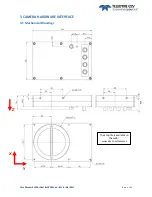
Страница 11: ...USER MANUAL ELIIXA 16K 8K CXP MONO REV K 06 2017 P A G E 11 3 CAMERA HARDWARE INTERFACE 3 1 Mechanical Drawings Z X Y The Step file is available on the web www e2v com cameras...

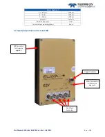
Страница 12: ...tput Connectors and LED Sensor alignment Z 9 4 mm 100 m X 9 mm 100 m Y 50mm 100 m Flatness 50 m Rotation X Y plan 0 1 Tilt versus lens mounting plane 50 m USB Connector For Firmware upgrade Trigger Co...

Страница 13: ...to a specific command from the Frame Grabber interface for shutting down up the power of the CoaxPress This solution with the complete reboot is the better solution to ensure a complete power On of t...

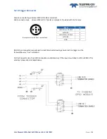
Страница 14: ...the Camera IN1 IN2 are connected respectively to Line0 Line1 and allow to get external line triggers or the forward Reverse Live indication On the Connector side the 120 termination is validated only...

Страница 15: ...nterferencethat may cause undesired operation This equipmenthas been tested and found to comply with the limits for Class A digital device pursuant to part 15 of the FCC rules These limits are designe...

Страница 16: ...e HR10A 7P 5P male or compliant There is no CDROM delivered with the Camera This User Manual and any other corresponding documents can be dowlaoded on the Web site Main Camera page www e2v com cameras...

Страница 17: ...GenICam API process to the application The Frame Grabber software is supposed to propose a feature Brother based on GenICam which lists and allows the modification of the parameters of the Camera This...

Страница 18: ...ing including 0 ElectronicBoardID 0x08000 32 RO Read Electronic Board ID ElectronicBoardTestStatus 0x08020 16 RO Read Electronic board status DeviceFirmwareVersion 0x02090 Boostrap 32 RO Get camera sy...

Страница 19: ...in from the sensor or Tap balance available only for integrator user mode StatusWarningUnderflow Bit 9 true if a an underflow occurs during FFC calibration or Tap balance available only for integrator...

Страница 20: ...SB 4 Set sensor mode to Binning DualLine 2SB 5 Set in HDR Mode MultiLineGain 0x08208 4 RW 0 Set MultiLine gain to x1 1 Set MultiLine gain to x1 2 not available if SensorMode 0 1S mode ReverseReading 0...

Страница 21: ...if the MultiLine Gain is set to see below this calculation will be AB BC 7 2 2 Binning modes The two binning modes give an output of 8k pixels 10x10 m As for the 2S mode the sensor manages the delay b...

Страница 22: ...ved by a factor of 2 7 2 4 HDR mode Only available on BH0 Models The High Dynamic Range Mode is using the top and bottom couple of lines of the sensor in a different way in order to get 2 different ex...

Страница 23: ...iven in Appendix C The following HDR Parameters are available only if the Sensor Mode is set to HDR HDR Mode 0 Output Single Line Bottom Only 1 Output Single Line Top Only 2 Output HDR Line HDR Ratio...

Страница 24: ...ble line period ScanDirectionMode 0x0820C 4 RW 0 Set scan direction to forward 1 Set scan direction to reverse 2 Set scan direction to Externally controlled direction via CC3 Camera Link CC3 0 forward...

Страница 25: ...3 2 CXP Trigger Line CXP specification allows the frame grabber to send triggers through the low speed link0 20MHz The CXP specification describes the behavior of the trigger where only the edge of th...

Страница 26: ...a is in 4S Sensor mode after changing of the scanning direction the 5 first following triggers will be ignored in order to reinitialize the Full Exposure Control mode Then the 3 following lines acquir...

Страница 27: ...l Conversion In TDI control of the exposure is not possible Only the full Exposure during the Line Period is possible In order to allow the User to control the exposure in this 4S Sensor mode Synchron...

Страница 28: ...e Switch 4s 2S is made in the conditions described above All the lines are sent even the double dark or double white at the transition depending on the direction of the transition Without Incorrect Li...

Страница 29: ...nd1 7 TimerEnd2 8 CounterStart1 9 CounterStart2 10 CounterEnd1 11 CounterEnd2 17 Line0 OR line1 18 Line0 AND Line1 19 RescalerLine TriggerActivation RW 25 23 Specifies the activation mode of the trigg...

Страница 30: ...ed Continuous TriggerMode Off TriggerMode On TriggerMode Off TriggerSource NA TriggerSource Line0 TriggerSource NA TriggerActivation NA TriggerActivation RisingEdg e TriggerActivation NA Mode 2 Off Co...

Страница 31: ...s two registers per line which can define a rescaler a multiplier and a divider With these two registers the end user can change the frequency of the line The generated line has always a 50 duty cycle...

Страница 32: ...or Line0 LineMode 0x08470 4 RW 31 Define the physical line as input Input 0 Input 1 Output LineInverter RW 30 Define the signal inversion 0 False 1 True LineDebounceFilter RW 29 Activate debounce filt...

Страница 33: ...nd 18 Timer1End 19 Timer2End CounterTriggerActivation RW 26 24 Select the type of activation for the trigger to start reset the counter 0 RisingEdge 1 FallingEdge 2 AnyEdge 3 LevelHigh 4 LevelLow Coun...

Страница 34: ...er was reset by a trigger or by an explicit CounterReset CounterResetSource 0x084C4 4 RW 31 27 Select the signal that reset the counter 0 Off 1 Software 2 Line0 3 Line1 4 Line2 CounterResetActivation...

Страница 35: ...the delay in s from the TimerTrigger to the actual Timer pulse output 0 31 30MHz step 1 30MHz TimerStatus RO 18 17 Get counter status 0 TimerIdle 1 TimerTriggerWait 2 TimerActive 3 TimerCompleted Time...

Страница 36: ...ailable x1 x2 and x4 A gain x1 in a 12 bits conversion is equivalent to x4 in 10 bits The Contrast Expansion both Digital Gain Offset will be automatically disabled if the LUT is enabled OUT Pixel X P...

Страница 37: ...4095 step 1 GainAbs GainSelector QuarterGain j 0x08610 to 0x0861C 4 4 RW tap j digital gain from 128 to 127 by step 1 0 0021dB Dynamically updated on AnalogAll gain changes Quarter Gain enable 0x0862...

Страница 38: ...he ROI Region of Interest Command address is 0x8628 This second command applies the Gain on the ROI in memory and this is immediately activated The ROI Gain is a online function that can be overlapped...

Страница 39: ...x1 x4 999 by step of 1 1024 Size CCDSize 2 PRNUValueSize Xml 2 RO Integer providing PRNU value size in byte FFCCalibrationCtrl 0x0880C 4 RW FFC calibration In Read Mode 0 finished 1 running In Write...

Страница 40: ...h precision of 1 2 o A Gain on 12 bits Unsigned Int U2 12 with a max gain value of x5 The calculation of the new pixel value is P P Off 1 Gain 1024 Gain 0 to 4095 The FFC processing can be completed w...

Страница 41: ...ter if the Target can t move This will remove the defects of the target itself Launch the FFC Enable the FFC You can save the FFC result both FPN PRNU in the same time in one of the 4 x FFC User Banks...

Страница 42: ...ted as too high or too low in the source image to be corrected efficiently The Calculation result will be proposed anyway as it s just a warning message The Status Register is the changed and displaye...

Страница 43: ...etSelector 1 2 3 4 5 6 7 8 User Banks SaveFFCToBank 0x08C14 4 WO Save current FFC including FPN and FFCGain to FFC bank number val from 1 to 8 val comes from FFC SetSelector 1 2 3 4 5 6 7 8 User Banks...

Страница 44: ...abled Feature CXP Size in bytes R W Description LUTEnable 0x08A00 4 RW 0 Disable LUT False 1 Enable LUT True LUTValueAll 0x30000 8K RW Memory containing LUT on 12 bits Size 2 12 2 LUTValueSize Xml 2 R...

Страница 45: ...NUAL ELIIXA 16K 8K CXP MONO REV K 06 2017 P A G E 45 LUT User Bank Usage At the power up Last User Bank used is loaded in RAM Ram Memory Save Load Upload load from to a Txt file User1 User2 User3 User...

Страница 46: ...vel values of Region of interest Pixel Min value PixelROIMin Minimum gray level pixel value on the whole region of interest Pixel Max Value PixelROIMax Maximum gray level pixel value on the whole regi...

Страница 47: ...e and a specific password is required to switch back the Camera in Integrator mode This password can be generated with a specific tool available from the hotline hotline cam e2v com Feature CXP Size i...

Страница 48: ...rator Bank UserSetSave 0x08C04 4 WO Save current UserSet to UserSet bank number val from 1 to 5 val comes from UserSetSelector 1 2 3 4 User Bank 5 Integrator Bank Not available in User Mode UserSetCon...

Страница 49: ...USER MANUAL ELIIXA 16K 8K CXP MONO REV K 06 2017 P A G E 49 APPENDIX...

Страница 50: ...e previous one In 12 bits the level reaches 4095 before switching down to 0 In 8 bits the level reaches 255 before switching down to 0 A 2 Test Pattern 2 Fixed Horizontal Ramps A 1 2 In 8 bits Full fo...

Страница 51: ...2 bits Medium format No Binning 16384 pixels An increment of 1 LSB is made for each pixel When it reaches 4095 turns back to 0 and starts again 250 255 260 265 270 275 280 285 290 295 300 250 260 270...

Страница 52: ...15 32 Pixel 16 33 Pixel 17 33 Pixel 31 33 Pixel 32 34 Pixel 511 63 Pixel 512 96 Pixel 513 96 Pixel 2047 255 Pixel 2048 32 30 35 40 45 50 55 60 65 70 0 100 200 300 400 500 0 10 20 30 40 50 60 70 80 90...

Страница 53: ...g Gain is applied by the gradient of the counting ramp see next chapter Gain Offset The conversion time depends on the pixel format 8 or 10 bits 6 s 12 bits 18 s This conversion is done in masked time...

Страница 54: ...e effective Exposure Time will be about Tintreal Tint Tx Td B 2 Synchronisation Modes with Maximum Exposure Time In these modes the rising edge of the Trigger internal or External starts the readout p...

Страница 55: ...is 12 bits The MSB are taken from the 8bits MSB of the Lines AB and divided by 16 max C 2 Example with Ratio 2 and 10bits output Line C 8bit Lines AB 8bit HDR bloc HDR Output 12 bit x 16 12bit 16 12bi...

Страница 56: ...ine The LUT could be used to compress the HDR output in 8bit Camera output illumination Saturation Lines AB Saturation Line C 1023 255 Lines AB used Line C used Camera 10b output without LUT Camera 8b...

Страница 57: ...rate shall have an attenuation that is less or equal to the following attenuation at its corresponding frequency example with Belden 1694A Cable Bit Rate Gbps Maximum Attenuation dB Frequency GHz Bel...

Страница 58: ...2650 SR 5 6 120 0061 0 33 X 0 26 0 38 X 453 mm 1004611 Accessories V mount 25mm macro extension tube Necessary to combine the whole lens system 20179 V mount to Leica adapter 20054 Unifoc 76 13048 Ada...

Страница 59: ...ter addresses 1 0 15B Rev E Characterization of the Forward Reverse feature 1 0 17 Rev F Documentation details about GenICam Triggers 1 0 17 Rev G New Documentation Template Low band Filter and 8 memo...

Отзывы: