


Page F-4
SPEED CONTROL
Repair and Service Manual
Read all of Section B and this section before attempting any procedure. Pay particular attention to all Notices, Cautions, Warnings and Dangers.
PEDAL BOX ADJUSTMENTS
Tool List
Qty.
Needle Nose Pliers...................................................... 1
Phillips Screwdriver ..................................................... 1
Open End Wrench, 9/16"............................................. 1
Open End Wrench, 1/2"............................................... 1
Open End Wrench, 7/16"............................................. 1
Open End Wrench, 3/8"............................................... 1
Allen Wrench, 1/8" ....................................................... 1
If any adjustments are made in the pedal box or accelerator
area, it is necessary to go back and perform the speed control
cable adjustment again. This
must
be done because any
adjustment made in the pedal box or accelerator area will inad-
vertently affect the cables.
Accelerator Pedal Arm Adjustment
Lift front of vehicle using procedures and safety informa-
tion in section ‘B’.
Confirm the accelerator pedal arm (1) contacts the
accelerator pedal bracket (2) when in the released posi-
tion (Ref Fig. 8). If there is no contact, loosen the jam
nut (3) and rotate the rod (4) until contact is made.
Note that the factory applies a thread sealant to the accelera-
tor rod threads before threading the rod into the clevis.
Fig. 8 Accelerator Pedal Arm Adjustment
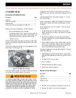
Micro Switch Adjustment
When the system is in correct adjustment, the micro
switch in the accelerator pedal box will click when the
top of the accelerator pedal moves approximately 1/2" -
5/8" (13 - 16 mm). The accelerator cable (as seen at the
rear axle) should have some slack present and not show
any movement until after the micro switch clicks.
To access the micro switch, remove the rocker panel, lift
the floor mat and remove the access cover from the floor
(Ref Fig. 4). Remove the screws (8) and cover (7) from
the pedal box (Ref Fig. 9).
Fig. 9 Pedal Box Micro Switch
Loosen the setscrew (9) in cam (10) using an 1/8" Allen
wrench. Loosen the jam nut (12) and move the cam to
adjust as needed (Ref Fig. 9). Adjust to permit 1/2" - 5/8"
(13 - 16 mm) of accelerator pedal travel before the micro
switch (11) clicks. Measure the distance at the top of the
pedal with the pedal arm contacting the pedal bracket.
Making sure the setscrew in the cam does not contact
the micro switch actuator. Tighten the setscrew (9) and
the jam nut (12) to the specified torque.
Be sure the accelerator pedal moves smoothly and the
accelerator cable pulls smoothly on the governor arm.
Replace the cover on the pedal box. Tap lightly to set the
cover before installing screws. Replace the access
cover on the floor. Replace floormat and rocker panel.
Road Test
Install the negative (-) battery cable.
Test drive the vehicle and confirm that the compression
spring adjustment results in the maximum governed
NOTICE
NOTICE
1
2
3
4
ITEM
TORQUE SPECIFICATION
9
45 - 55 in. lbs (5 - 6 Nm)
12
10 - 11 ft. lbs (14 - 15 Nm)
7
8
9
10
12
11