


Page E-16
FRONT SUSPENSION AND STEERING
Repair and Service Manual
Read all of Section B and this section before attempting any procedure. Pay particular attention to all Notices, Cautions, Warnings and Dangers.
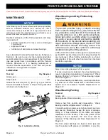
Loosen the steering wheel retaining nut (6) two to three
turns (Ref. Fig. 21). DO NOT REMOVE NUT AT THIS
TIME. Apply upward pressure to the steering wheel.
Place a plastic faced hammer against the steering wheel
nut and strike plastic faced hammer sharply with a ball
peen hammer.
Do not strike steering nut or end of steering shaft directly
with ball peen hammer. Internal damage to rack and pin-
ion unit can result.
When steering wheel is loosened, remove retaining nut
and remove steering wheel.
Prior to replacement, assemble the replacement steer-
ing wheel by aligning the retaining tabs on the rear collar
hub (7) with slots in back of steering wheel. Squeeze
tabs to allow insertion of hub.
Do not force
. Squeeze
hub on top and bottom to fully seat.
Replace steering wheel by first lightly coating the splines
of the steering shaft with a commercially available anti-
seize compound. With the vehicle wheels in the straight
ahead position, align the steering wheel on the steering
shaft and slide wheel on shaft. Tighten the steering
wheel nut (6) to 15 - 20 ft. lbs. (20 - 27 Nm) torque.
Inspect the four retaining tabs on the clipboard (5) for
white stress lines (Ref. Fig. 20). If stress lines are
present, replace clipboard. Install by carefully pressing,
first the top two, then the bottom two retaining tabs into
the matching slots in steering wheel.
Steering Shaft and Column Replacement
Tool List
Qty. Required
Ratchet, 1/2" drive ....................................................... 1
Socket, 3/4", 1/2" drive ................................................ 1
Socket, 13 mm, 3/8" drive ........................................... 1
Ratchet, 3/8" drive ....................................................... 1
Socket, 9/16", 1/2" drive .............................................. 1
Snap ring pliers............................................................ 1
Bearing separator ........................................................ 1
Gear puller................................................................... 1
Arbor press .................................................................. 1
Bearing driver set ........................................................ 1
Torque wrench, 1/2" drive, ft. lbs. ................................ 1
Torque wrench, 3/8" drive, in. lbs. ............................... 1
Wheel bearing grease .............................................. AR
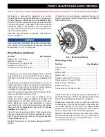
To remove steering shaft (4) (Ref. Fig. 22), remove the
steering wheel. “Steering Wheel Replacement” on Page
E-15
Loosen front wheels. Lift and support front of vehicle per
SAFETY section and remove front wheels.
Remove the bolt (1) and washer (2) that secures the
intermediate shaft (3) to the steering shaft (4).
Fig. 22 Steering Shaft and Column
Remove the four bolts (5) and washers (6) that secure
the steering column (7) to the chassis and remove the
column.
Remove large retaining ring (8) on bottom end of column
and pull shaft and bearing (9) out as an assembly. Slide
wave washer (10) out bottom end of steering column
and keep for reuse.
Remove small retaining ring (11) and press bearing from
steering shaft.
To assemble steering shaft, first press new bearing onto
shaft until it stops against shoulder. Then, with small
retaining ring oriented with arch up, slide ring onto shaft
as far as possible using snap ring pliers (Ref. Fig. 23).
Use fingers to push retaining ring fully into groove.
4
5
6
12
7
10
9
11
3
8
1
2


