


MECHANICAL BRAKES
Read all of Section B and this section before attempting any procedure. Pay particular attention to all Notes, Cautions and Warnings
Install the actuator components, adjuster components
and brake shoes. See 'Brake Shoe and Adjuster Replace
ment' on page M-17. If the brake shoes and drum are not
to be replaced, sand the friction surfaces lightly with
emery cloth to remove any foreign material.
CAUTION
Be sure that the adjusting screw is
screwed into the star wheel nut until
only 1 - 2 threads are exposed (Ref Fig. 25 on page M-18). If the
brake shoes are replaced, replace the three brake springs and
the adjuster components.
Replace the springs one side at a time, using the other
side as a guide.
Install brake drum as described in 'Brake Drum Removal
and Installation'.
Repeat on other side of vehicle.
Adjust the brake pedal free travel. See 'Adjusting Brake
Pedal Free Travel' on page M-14.
Backing Plate/Entire Wheel Brake Assembly
Removal and Installation
Remove the four bolts (1) and lock nuts (2) securing the
wheel brake backing plate to the flange on the axle tube
(Ref Fig. 23 on page M-17).
Fig. 23 Backing Plate Removal and Installation
Remove the clevis pin securing the brake cable to the
brake lever.
Installation is the reverse of removal. Connect the brake
cable to the wheel brake with the clevis pin installed from
the top down and a new cotter pin. Install the brake
assembly or backing plate to the axle tube flange. Install
new hardware (locknut should only be used once) and
tighten to 23 - 28 ft. lbs (31 - 38 Nm) torque.
Brake Shoe and Adjuster Replacement
I
NOTE
I
ft is recommende'! that when bra�e shoes are
�-
---�-
replaced, the ad1usters and spnngs also be
replaced. It is good practice to do one side at a time, using the
other side for reference.
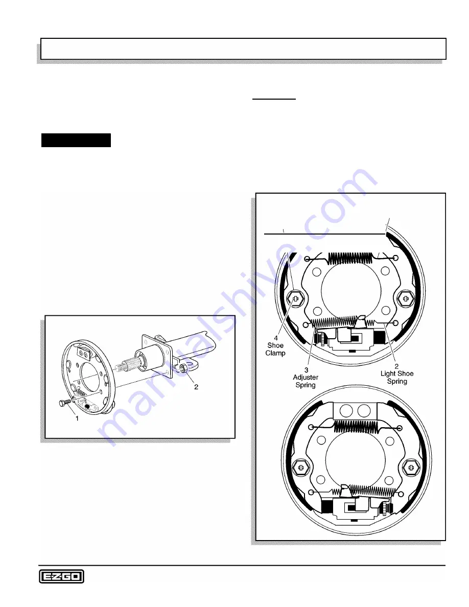
Remove the three brake shoe springs and discard (1, 2,
3). Note the location of the heavy spring and the adjuster
spring (Ref Fig. 24 on page M-17). Hold the shoe clamp
pin (4) and compress and rotate the shoe clamp (5) 90
°
to release it from the shoe clamp pin. Remove the brake
shoes, adjusters and remaining components.
Heavy Shoe Spring
1
Shoe��
Pin
Fig. 24 Brake Shoes and Springs
Repair and Service Manual
Page M-17
Содержание 4 CADDY 1999
Страница 6: ...TABLE OF CONTENTS Notes __________________________ _ Page iv Repair and Service Manual...
Страница 10: ...SAFETY INFORMATION Notes _________________________ _ Page viii Repair and Service Manual...
Страница 26: ...SAFETY Notes _ _ ___________________________ _ Page B ii Repair and Service Manual...
Страница 48: ...BODY Notes _ _ ___________________________ _ Page C ii Repair and Service Manual...
Страница 56: ...WHEELS AND TIRES Notes __________________________ _ Page D ii Repair and Service Manual...
Страница 60: ...FRONT SUSPENSION AND STEERING Notes ________________________ _ Page E ii Repair and Service Manual...
Страница 72: ...SPEED CONTROL Notes _ _ ________________________ _ Page F ii Repair and Service Manual...
Страница 80: ...ENGINE Notes _ _ __________________________ _ Page G ii Repair and Service Manual...
Страница 94: ...FUEL SYSTEM Notes _ _ _________________________ _ Page H ii Repair and Service Manual...
Страница 104: ...CONTINUOUSLY VARIABLE TRANSMISSION CVT Notes _______________________ _ Page J ii Repair and Service Manual...
Страница 110: ...ELECTRICAL Notes _ _ _________________________ _ Page K ii Repair and Service Manual...
Страница 120: ...ACCESSORY WIRING Notes __________________________ _ Page L ii Repair and Service Manual...
Страница 148: ...REAR SUSPENSION Notes __________________________ _ Page N ii Repair and Service Manual...
Страница 154: ...REAR AXLE Notes _ _ ___________________________ _ Page P ii Repair and Service Manual...
Страница 158: ...PAINT Notes _ _ ___________________________ _ Page Q ii Repair and Service Manual...
Страница 162: ...TROUBLESHOOTING Notes _ _ ________________________ _ Page R ii Repair and Service Manual...
Страница 170: ...LIMITED WARRANTY Notes __________________________ _ Page S ii Repair and Service Manual...
Страница 176: ...LIMITED WARRANTY Notes __________________________ _ Page S 6 Repair and Service Manual...
Страница 178: ...GENERAL SPECIFICATIONS Notes _________________________ _ Page T ii Repair and Service Manual...


