


ACCESSORY WIRING
Read all of Section Band this section before attempting any procedure. Pay particular attention to all Notes, Cautions and Warnings
POWER SUPPLY
Tool List
Qty. Required
OVOM
......................................................................... 1
1. Check for loose or bare wires
Check for loose wires at each terminal connection
and for worn insulation or bare wires touching the
frame.
Bare wires may cause a short circuit.
I
NOTE
I
"any DVOM readings indicate a faulty wire, it
·
·
is recommended that the condition of the termi
nals and wire junction be examined. A faulty wire should be
replaced with one of the same gauge and color and wired
between the correct components and wire tied to the harness
bundle. The faulty wire should be cut back close to the harness
and the ends protected with vinyl electrical tape.
2. Check battery condition
Check for adequate battery volts (nominal 12 VOC)
by setting OVOM to 30
voe
range and place the red
probe (+) on the battery post with the green wire
attached. Place the black probe(-) on the battery post
with the black wire attached. A reading of 11
voe
or
greater indicates adequate battery condition. No
reading indicates (a) a poor connection between the
probes and the battery terminals; (b) a faulty OVOM.
A voltage reading below 11 volts indicates poor bat
tery condition and the vehicle should be recharged
before proceeding with the test.
I
NOTE
I
D�e. to the resistance of the w�res involved
within the harness, voltage readings may be
somewhat lower than battery voltage. A reading of 1 volt below
battery voltage is acceptable.
3. Check power wire
Firmly attach the black probe (-) to the battery post
with the black wire attached and the red probe (+) to
the green wire terminal at the fuse block. A reading of
battery voltage indicates that the power wire is in
good condition.
4. Check fuse
Place the red probe (+) to each wire terminal on the
fuse block. A reading of battery voltage indicates that
the fuse is in good condition. No reading indicates a
faulty fuse; replace with a good 15 amp fuse.
ACCESSORY WIRING
After determining that there is power to the fuse panel,
and the fuse is good, continue checking the circuit using
the procedures previously used to check the power sup
ply, i.e. loose or rusted connections, bare wires, continu
ity of the wiring from terminal to terminal, operating
condition of switch, etc.
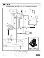
Use the wiring diagram (Ref Fig. 2 on page L-2) to check
correct wiring and wire routing. If there is power at the
fuse end of the wire, there must also be power at the
other end of the wire at the switch or electrical accessory,
and eventually at the ground connection. Electricity must
flow from the fuse panel through the full length of the cir
cuit to the ground connection. Any interruption of electri
cal flow must be corrected, whether by repairing or
replacing the wire, the switch or accessory.
Repair and Service Manual
Page L-3
Содержание 4 CADDY 1999
Страница 6: ...TABLE OF CONTENTS Notes __________________________ _ Page iv Repair and Service Manual...
Страница 10: ...SAFETY INFORMATION Notes _________________________ _ Page viii Repair and Service Manual...
Страница 26: ...SAFETY Notes _ _ ___________________________ _ Page B ii Repair and Service Manual...
Страница 48: ...BODY Notes _ _ ___________________________ _ Page C ii Repair and Service Manual...
Страница 56: ...WHEELS AND TIRES Notes __________________________ _ Page D ii Repair and Service Manual...
Страница 60: ...FRONT SUSPENSION AND STEERING Notes ________________________ _ Page E ii Repair and Service Manual...
Страница 72: ...SPEED CONTROL Notes _ _ ________________________ _ Page F ii Repair and Service Manual...
Страница 80: ...ENGINE Notes _ _ __________________________ _ Page G ii Repair and Service Manual...
Страница 94: ...FUEL SYSTEM Notes _ _ _________________________ _ Page H ii Repair and Service Manual...
Страница 104: ...CONTINUOUSLY VARIABLE TRANSMISSION CVT Notes _______________________ _ Page J ii Repair and Service Manual...
Страница 110: ...ELECTRICAL Notes _ _ _________________________ _ Page K ii Repair and Service Manual...
Страница 120: ...ACCESSORY WIRING Notes __________________________ _ Page L ii Repair and Service Manual...
Страница 148: ...REAR SUSPENSION Notes __________________________ _ Page N ii Repair and Service Manual...
Страница 154: ...REAR AXLE Notes _ _ ___________________________ _ Page P ii Repair and Service Manual...
Страница 158: ...PAINT Notes _ _ ___________________________ _ Page Q ii Repair and Service Manual...
Страница 162: ...TROUBLESHOOTING Notes _ _ ________________________ _ Page R ii Repair and Service Manual...
Страница 170: ...LIMITED WARRANTY Notes __________________________ _ Page S ii Repair and Service Manual...
Страница 176: ...LIMITED WARRANTY Notes __________________________ _ Page S 6 Repair and Service Manual...
Страница 178: ...GENERAL SPECIFICATIONS Notes _________________________ _ Page T ii Repair and Service Manual...


