background image

3 - 23

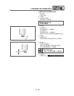
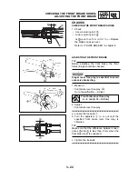
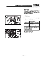
ADJUSTING THE PARKING BRAKE

CHK

ADJ

ADJUSTING THE PARKING BRAKE

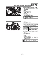
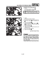
1. Check:

• parking brake cable end length 

Out of specification 

o

 Adjust.

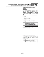
Parking brake cable end length

53.0 ~ 57.0 mm (2.09 ~ 2.24 in)

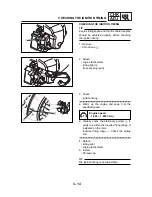
2. Adjust:

• parking brake cable end length 

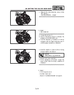
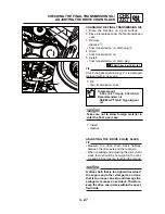
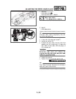
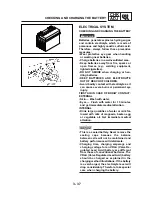
a. Loosen the locknut 

 and adjusting bolt

.

b. Loosen the locknut 

.

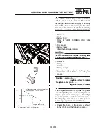
c. Turn the adjusting nut 

 in direction 

 or

 until the specified brake cable end

length is obtained.

d. Tighten the locknut     . 
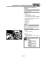
e. Slowly turn the adjusting bolt clockwise until

resistance is felt.

f. Turn it 1/8 counterclockwise.
g. Tighten the locknut 

.

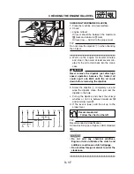
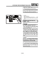
After this adjustment is performed, lift the
rear wheels off the ground by placing a
block under the engine, and spin the rear
wheels to ensure there is no brake drag. If
any brake drag is noticed perform the
above steps again.

16 Nm (1.6 m•kg, 11 ft•lb)

WARNING

Содержание ATV6A 90

Страница 1: ...SERVICE MANUAL ATV6A 90 VIPER 90 E TON POWER...

Страница 2: ...SERVICE MANUAL 2009 by E TON POWER TECH CO LTD First edition May 2009 All rights reserved Any reproduction or unauthorized use without the written permission of E TON POWER TECH CO LTD is expressly pr...

Страница 3: ...res will be forwarded to all authorized E TON dealers and will appear in future editions of this manual where applicable TIP Designs and specifications are subject to change without notice IMPORTANT I...

Страница 4: ...of symbol marks The meanings of the symbol marks are given on the next page 4 A job instruction chart accompanies the exploded diagram providing the order of jobs names of parts notes in jobs etc 5 F...

Страница 5: ...l Torque Wear limit clearance Engine speed Electrical data V A Symbols to in the exploded diagrams indicate the types of lubricants and lubrication points Apply engine oil Apply gear oil Apply molybde...

Страница 6: ...TABLE OF CONTENTS SPECIFICATIONS 2 PERIODIC CHECKS AND ADJUSTMENTS 3 ENGINE 4 CARBURETOR 5 CHASSIS 6 ELECTRICAL 7 GENERAL INFORMATION 1 TROUBLESHOOTING 8...

Страница 7: ...TION NUMBER 1 1 ENGINE SERIAL NUMBER 1 1 IMPORTANT INFORMATION 1 2 PREPARATION FOR REMOVAL AND DISASSEMBLY 1 2 REPLACEMENT PARTS 1 2 GASKETS OIL SEALS AND O RINGS 1 2 LOCK WASHERS PLATES AND COTTER PI...

Страница 8: ...IONS 2 13 TIGHTENING TORQUES 2 15 ENGINE TIGHTENING TORQUES 2 15 CHASSIS TIGHTENING TORQUES 2 16 HOW TO USE THE CONVERSION TABLE 2 18 GENERAL TIGHTENING TORQUE SPECIFICATIONS 2 18 LUBRICATION POINTS A...

Страница 9: ...ANING THE AIR FILTER ELEMENTS 3 19 CLEANING THE SPARK ARRESTER 3 20 CHASSIS 3 22 CHECKING THE FRONT BRAKE SHOES 3 22 ADJUSTING THE FRONT BRAKE 3 22 CHECKING THE REAR BRAKE FLUID LEVEL 3 24 CHECKING TH...

Страница 10: ...THE ROCKER ARMS AND CAMSHAFT 4 12 REMOVING THE VALVES AND VALVE SPRINGS 4 12 CHECKING THE CAMSHAFT 4 13 CHECKING THE ROCKER ARMS AND ROCKER ARM SHAFTS 4 13 CHECKING THE VALVES AND VALVE SPRINGS 4 15 I...

Страница 11: ...CKING THE PIECE SLIDER 4 39 CHECKING THE DRIVEN PULLEY 4 39 ASSEMBLING THE PRIMARY SHEAVE 4 40 ASSEMBLING THE SECONDARY SHEAVE 4 41 INSTALLING THE BELT DRIVE 4 42 TRANSMISSION 4 55 CHECKING THE TRANSM...

Страница 12: ...CARBURETOR 5 1 DISASSEMBLING THE CARBURETOR 5 4 CHECKING THE CARBURETOR 5 4 ASSEMBLING THE CARBURETOR 5 6 INSTALLING THE CARBURETOR 5 7 MEASURING AND ADJUSTING THE FUEL LEVEL 5 8 CHAPTER 5 CARBURETOR...

Страница 13: ...S 6 9 REAR AXLE AND REAR AXLE HUB 6 11 REAR AXLE AND REAR AXLE HUB 6 11 REMOVING THE REAR AXLE 6 13 CHECKING THE REAR AXLE 6 14 CHECKING THE DRIVEN SPROCKET 6 14 CHECKING THE BRAKE DISC 6 14 INSTALLIN...

Страница 14: ...LES 6 37 REMOVING THE STEERING KNUCKLES 6 38 REMOVING THE TIE RODS 6 38 CHECKING THE TIE RODS 6 38 CHECKING THE STEERING KNUCKLES 6 38 INSTALLING THE TIE RODS 6 39 FRONT ARMS AND FRONT SHOCK ABSORBER...

Страница 15: ...7 5 CIRCUIT DIAGRAM 7 5 TROUBLESHOOTING 7 6 ELECTRIC STARTING SYSTEM 7 10 CIRCUIT DIAGRAM 7 10 STARTING CIRCUIT OPERATION 7 11 TROUBLESHOOTING 7 12 STARTER MOTOR 7 14 CHECKING THE STARTER MOTOR 7 15 A...

Страница 16: ...ERFORMANCE 8 2 POOR MEDIUM AND HIGH SPEED PERFORMANCE 8 2 FAULTY CLUTCH 8 3 ENGINE OPERATES BUT VEHICLE WILL NOT MOVE 8 3 CLUTCH SLIPPING 8 3 POOR STARTING PERFORMANCE 8 3 POOR SPEED PERFORMANCE 8 3 O...

Страница 17: ...MACHINE IDENTIFICATION VEHICLE IDENTIFICATION NUMBER The vehicle identification number is stamped into the left side of the frame MACHINE IDENTIFICATION 1 1 The engine serial number is stamped on the...

Страница 18: ...embly 4 During disassembly clean all of the parts and place them in trays in the order of dis assembly This will speed up assembly and allow for the correct installation of all parts 5 Keep all parts...

Страница 19: ...bricate the oil seal lips with a light coat of lithium soap based grease Oil bearings liberally when installing if appro priate Oil seal Do not spin the bearing with compressed air because this will d...

Страница 20: ...3 Check all connections Loose connection Connect properly If the pin 1 on the terminal is flattened bend it up 4 Connect lead coupler connector Make sure all connections are tight 5 Check continuity...

Страница 21: ...88 cm 5 37 cu in 3 Bore x stroke Compression ratio 10 2 1 Standard compression pressure at sea level 1250 kPa 12 5 kg cm2 181 3 psi at 1 000r min Electric starter kick starter Starting system Lubricat...

Страница 22: ...ndary reduction system Spur Secondary reduction ratio 41 15 45 13 9 46 Third reduction system Chain drive Third reduction ratio 28 13 2 154 Transmission type V belt automatic Chassis Frame type Steel...

Страница 23: ...on Suspension Front suspension Single A arm Independent Rear suspension Swing arm Shock absorber Front shock absorber Coil spring oil damper Rear shock absorber Coil spring oil damper Wheel travel Fro...

Страница 24: ...0 01 mm 0 0004 in Camshaft Drive method Chain drive Left Cam dimensions Intake A 25 683 25 843 mm 1 0111 1 0174 in 25 583 mm 1 0072 in B 20 985 21 015 mm 0 8262 0 8274 in 20 886 mm 0 8223 in Exhaust...

Страница 25: ...side diameter Guide inside diameter Item Standard Limit B C D A Head Diameter Face Width Seat Width Margin Thickness IN 20 9 21 1 mm 0 8228 0 8307 in EX 18 9 19 1 mm 0 7441 0 7520 in IN 1 50 1 80 mm 0...

Страница 26: ...pring Free length IN 30 00 mm 1 18 in 27 00 mm 1 06 in EX 30 00 mm 1 18 in 27 00 mm 1 06 in Compressed pressure installed IN 39 14 47 77 N at 22 45 mm 3 99 4 87 kg 8 80 10 74 lb at 0 884 in EX 39 14 4...

Страница 27: ...1 2 mm 0 05 in 2 0 1 2 mm 0 05 in Compressed pressure installed 73 75 90 03 N at 25 45 mm 7 52 9 18 kg 16 57 20 23 lb at 1 00 in 73 75 90 03 N at 25 45 mm 7 52 9 18 kg 16 57 20 23 lb at 1 00 in IN Ti...

Страница 28: ...6in Limit Standard Item Piston rings Top ring Type Dimensions B T End gap installed Side clearance installed 2nd ring Type Dimensions B T End gap installed Side clearance T B B T Oil ring Dimensions B...

Страница 29: ...m 0 669in 107 5 mm 4 23in 30 5 mm 18 0 mm 0 709 in 107 0 107 2 mm 0 587 0 594 in 14 9 15 1 mm Transmission V belt automatic Transmission type Primary reduction system Primary reduction ratio Secondary...

Страница 30: ...0 0083 in 0 28 mm 0 0110 in Oil pump housing to inner rotor and outer rotor clearance 0 06 0 11 mm 0 14 0 21 mm 0 04 0 12mm 0 0024 0 0043 in 0 20 mm 0 0079 in Lubrication chart Pressure feed Splashed...

Страница 31: ...al Steel Rim runout limit radial 2 0 mm 0 08 in lateral 2 0 mm 0 08 in Rear wheel Type Panel wheel Rim size 8 x 7 AT Rim material Steel Rim runout limit radial 2 0 mm 0 08 in lateral 2 0 mm 0 08 in Dr...

Страница 32: ...isc brake Type Disc outside diameter thickness 2 7 mm 0 11 in Brake disk maximum deflection 0 15 mm 0 006 in Pad thickness inner 3 7 mm 0 15 in DOT 4 30 23 mm 1 19 in 12 7 mm 0 50 in Single 190 0 3 2...

Страница 33: ...del manufacturer C0410 A26 3000 EYE Ignition coil Model manufacturer C0510 A26 3000 SHIHLIN Minimum spark gap 6 mm 0 24 in Primary winding resistance 0 19 0 23 at 20 C 68 F Secondary winding resistanc...

Страница 34: ...3 5 mm 7 0 mm 0 28 in 1 0 3 0 N Brush overall length 0 14 in Spring force 102 306gf 3 60 10 80 oz 19 5 mm 22 0 mm 0 87 in Commutator diameter 0 77in 6 mm 0 06 in 1 Mica undercut Starter relay C585A L...

Страница 35: ...nsioner plug Bolt Nut M5 2 9 0 9 6 5 Nut Gear oil pump driven Hole cap tap adjusting Bolt M30 1 8 0 8 5 8 M8 1 25 2 5 18 M5 2 2 0 2 1 4 M5 2 5 0 5 3 6 Bolt M6 8 12 1 2 8 7 Bolt Screw Screw Screw Screw...

Страница 36: ...ne lower stay and engine Engine and frame Engine lower stay and frame Swingarm pivot shaft and frame Front shock absorber front arm Steering stem bushing and frame M8 Steering knuckle and front arm Re...

Страница 37: ...ing the nuts apply locking agent LOCTITE to rear axle threads 2 Tighten the inside nut to 60 Nm 6 0 m kg 43 4 ft lb t u n e d i s n i e h t g n i d l o h e l i h w b l t f 3 2 1 g k m 0 7 1 m N 0 7 1...

Страница 38: ...should be at room temperature A Distance between flats B Outside thread diameter Ex METRIC MULTIPLIER IMPERIAL mm x 0 03937 in 2 mm x 0 03937 0 08 in METRIC TO IMPERIAL Torque Metric unit Multiplier I...

Страница 39: ...Piston pin outside surface Crankshaft journal Camshaft profile journal Valve stem IN EX Valve stem seal Valve stem end IN EX Valve lifter Oil pump assembly inside Oil pipe union bolt thread and surfa...

Страница 40: ...nt Lubricant LS Primary sheave inside Collar Solid bush Secondary fixed inner surface Secondary sheave torque cam ditch Gasket Cylinder head cover Stopper guide Cylinder head cover Crankcase mating su...

Страница 41: ...OIL FLOW DIAGRAMS Camshaft Crankshaft Oil pump Oil filter 1 2 3 4 2 21 OIL FLOW DIAGRAMS SPEC SPEC...

Страница 42: ...e check hose Wire harness Carburetor air vent hose Front brake cables Handlebar switch lead Rear brake switch lead Fuel overflow Choke cable 0 Fuel hose Fuel tank breather hose A Crankcase breather ho...

Страница 43: ...tch lead with a plastic band Insert the fuel tank breather hose into the hole in the handlebar cover C E F D Fasten the fuel overflow hose and carburetor air vent hose with a metal band Be sure to not...

Страница 44: ...G H Brake fuel tube with a clip 2 24 CABLE ROUTING SPEC SPEC Route the parking brake cable under the cross pipe and left of the steering column as shown in the illustration...

Страница 45: ...Positive starter motor lead B Positive battery lead C Negative battery lead D Starter motor E Generator lead F Main switch lead G H Ignition coil I Rectifier regulator Negative starter motor lead J K...

Страница 46: ...main switch lead heater control switch lead and with a plastic band C Fasten the wire harness negative battery lead and starter motor lead with a plastic band D Fixed the negative battery lead and ne...

Страница 47: ...ake cable right Front brake cable left Fuel tank breather hose Positive battery lead Choke cable Handlebar switch Throttle cable Negative battery lead 1 12 13 2 3 4 5 6 Battery 7 8 9 10 11 Main fuse 2...

Страница 48: ...the side of the battery Connect the positive battery lead to the battery so that the lead contacts the battery case Fasten the handlebar switch lead rear brake switch lead and choke cable with a plas...

Страница 49: ...rottle cable 1 2 3 4 5 6 7 Fasten the handlebar switch lead rear brake switch lead and choke cable with a plastic band A Front brake cable right Front brake cable left A Ignition coil 2 29 CABLE ROUTI...

Страница 50: ...ng speed and adjust if neces sary 5 Crankcase breather system Check breather hose for cracks or other damage and replace if necessary 6 Exhaust system Check for leakage and replace gasket s if neces s...

Страница 51: ...ation and adjust or replace if neces Lubricate sary 19 Throttle lever hous ing and cable Check operation and correct if necessary Check throttle cable free play and adjust if neces sary Lubricate thro...

Страница 52: ...4 Parking brake cable 1 5 Choke cable 1 6 Rear brake hose 7 Upper handlebar holder 8 Handlebar 1 1 1 3 3 HANDLEBAR SEAT FENDERS AND FUEL TANK CHK ADJ HANDLEBAR 5 3 4 6 7 8 x4 Refer to INSTALLING THE...

Страница 53: ...or installation reverse the removal pro cedure 1 Seat 1 Pull back the seat lock lever than pull up on the rear of the seat 2 Front panel 1 3 Footrest board L 1 4 Footrest board R 1 Refer to HANDLEBAR...

Страница 54: ...AND FRONT PANEL 1 Front body cover 1 2 Front fender L 1 3 Front fender R 1 4 Air cleaner joint clamp screw 1 Loosen For installation reverse the removal pro cedure Refer to HANDLEBAR Handlebar 3 5 CHK...

Страница 55: ...Handlebar 1 Wire harness and main fuse 1 2 Negative battery lead 1 3 Positive battery lead 1 Disconnect First disconnect the negative lead then disconnect the positive lead 4 Battery 1 1 1 1 5 Rear b...

Страница 56: ...front panel Refer to SEAT AND FRONT PANEL Front fender Refer to FRONT FENDER 1 Fuel hose 2 Disconnect Before disconnecting the fuel hose turn the fuel cock to OFF 2 Fuel tank 1 For installation rever...

Страница 57: ...at top dead center TDC on the compression stroke 2 Measure valve clearance Out of specification Adjust a Turn the crankshaft clockwise with a wrench b Align the T mark on the rotor with the stationar...

Страница 58: ...lockwise with the tappet adjusting tool until the proper clearance is obtained d Hold the adjuster to prevent it from moving and then tighten the locknut e Measure the valve clearance f If the clearan...

Страница 59: ...engine idling speed a Turn the throttle stop screw in or out until the specified idling speed is obtained 5 Detach engine tachometer Turning right Idling speed becomes higher Turning left Idling speed...

Страница 60: ...e locknut on the carburetor side c Turn the adjuster in or out until the cor rect free play is obtained d Tighten the locknut e Push in the adjuster cover After adjusting the free play turn the han dl...

Страница 61: ...ter length is obtained c Tighten the locknut WARNING Particularly for a beginner rider the speed limiter should be screwed in com pletely Screw it out little by little as their riding technique improv...

Страница 62: ...e Normal color is a medium to light tan color 4 Clean spark plug with a spark plug cleaner or wire brush Standard spark plug CR7HSA NGK 5 Measure spark plug gap Use a wire gauge or thickness gauge Out...

Страница 63: ...Check ignition timing a Warm up the engine and keep it at the specified speed b Visually check the stationary pointer to verify it is within the required firing range indicated on the rotor Incorrect...

Страница 64: ...plug Before removing a spark plug use com pressed air to blow away any dirt accumu lated in the spark plug well to prevent it from falling into the cylinder 5 Attach compression gauge 6 Measure compr...

Страница 65: ...ts Carbon deposits Eliminate d If the compression pressure is below the minimum specification squirt a few drops of oil into the cylinder and measure again Refer to the following table 7 Install spark...

Страница 66: ...g the dipstick b Screw the dipstick completely out and wipe the dipstick clean then just rest the dipstick in the hole c Pull up the dipstick and check the oil level whether or not it is between maxim...

Страница 67: ...engine oil drain bolt 7 Fill crankcase with the specified amount of the recom mended engine oil 8 Install dipstick 9 Start the engine warm it up for several min utes and then turn it off 10 Check engi...

Страница 68: ...ir filter excessive piston and or cylinder wear may result This model is equipped with two air filter elements one located on the left side and one located on the right side of the air box 4 Check spo...

Страница 69: ...Tighten bolt 8 Install Air filter case covers Make sure its sealing surface matches the sealing surface of the case so there is no air leak CLEANING THE SPARK ARRESTER 1 Clean spark arrester Select a...

Страница 70: ...e any carbon deposits from the spark arrester portion of the tailpipe and the inner contact surfaces of the muffler d Insert the spark arrester into the muffler and align the screw holes e Insert the...

Страница 71: ...Turn the adjusters in or out until the specified front brake lever free play is obtained Make sure that the difference between clear ances and is less than 2 mm when the front brake lever is squeezed...

Страница 72: ...c Turn the adjusting nut in direction or until the specified brake cable end length is obtained d Tighten the locknut e Slowly turn the adjusting bolt clockwise until resistance is felt f Turn it 1 8...

Страница 73: ...r Water will significantly lower the boiling point of the brake fluid and could cause vapor lock Brake fluid may damage painted surfaces and plastic parts Therefore always clean up any spilt brake flu...

Страница 74: ...SE 1 Remove seat front fender Refer to SEAT FENDERS AND FUEL TANK 2 Check CHECKING THE REAR BRAKE PADS 1 Check brake pads Wear indicators almost touch the brake disc Replace the brake pads as a set Re...

Страница 75: ...Connect a clear plastic hose tightly to the bleed screw d Place the other end of the hose into a con tainer e Slowly apply the brake lever or brake pedal several times f Fully squeeze the brake lever...

Страница 76: ...0 32 US qt Recommended oil SAE80 API GL 4 Hypoid gear oil ADJUSTING THE DRIVE CHAIN SLACK Measure the drive chain slack halfway between the drive axle and the rear axle When checking and adjusting the...

Страница 77: ...tion To loosen the drive chain turn the drive chain adjusting nut in direction b a d Tighten the locknut e Tighten the rear wheel axle pinch bolts Excessive chain slack will overload the engine and ot...

Страница 78: ...ar to the left and or right until it stops completely then slightly move the handlebar slightly in the opposite direction Tie rod end s have vertical play Replace the tie rod end s Refer to STEERING S...

Страница 79: ...rks f Calculate the toe in using the formula given below g If the toe in is incorrect adjust it Forward 3 Adjust toe in Be sure that both tie rods are turned the same amount If not the machine will dr...

Страница 80: ...hock absorbers up and down for several times Unsmooth operation Replace the front rear shock absorber assembly Refer to ADJUSTING THE SHOCK ABSORBERS Front shock absorber Rear shock absorber a Mark bo...

Страница 81: ...t spring preload a Turn the adjusting ring in direction or with the spanner wrench Direction Spring preload is increased suspension is harder Direction Spring preload is decreased suspension is softer...

Страница 82: ...0 25 kgf cm2 3 6 psi 2 Tire pressure below the minimum speci fication could cause the tire to dislodge from the rim under severe riding condi tions The following are minimums Front 22 kPa 0 22 kgf cm...

Страница 83: ...e pressure may adversely affect the handling of this machine and may cause loss of control Maintain proper tire pressures Set tire pressures when the tires are cold Tire pressures must be equal in bot...

Страница 84: ...Front and rear 3 mm 0 12 in CHECKING THE WHEELS 1 Check wheel Damage bends Replace Always balance the wheel when a tire or wheel has been changed or replaced Never attempt even small repairs to the w...

Страница 85: ...on Lubricate or replace Hold the cable end up and apply several drops of lubricant to the cable Recommended lubricant Lithium soap base grease LUBRICATING THE LEVERS STEERING SHAFT AND STEERING KNUCKL...

Страница 86: ...NTACT EXTERNAL Skin Wash with water Eyes Flush with water for 15 minutes and get immediate medical attention INTERNAL Drink large quantities of water or milk fol lowed with milk of magnesia beaten egg...

Страница 87: ...battery ter minals The charge state of an VRLA Valve Regulated Lead Acid battery can be checked by measur ing its open circuit voltage i e the voltage when the positive terminal is disconnected No ch...

Страница 88: ...o not plug in the battery charger until the bat tery charger leads are connected to the battery Before removing the battery charger lead clips from the battery terminals be sure to turn off the batter...

Страница 89: ...voltage of an VRLA Valve Regulated Lead Acid battery stabilizes about 30 minutes after charging has been completed Therefore wait 30 minutes after charging is completed before measuring the open circu...

Страница 90: ...he open circuit voltage Refer to CHECKING AND CHARGING THE BATTERY If the required charging time exceeds 5 hours it is advisable to check the charging amperage after 5 hours If there is any change in...

Страница 91: ...charge an VRLA battery A variable voltage charger is recommended Set the charging time to a maxi mum of 20 hours Leave the battery unused for more than 30 minutes before measuring its open circuit vol...

Страница 92: ...then the negative battery lead 8 Check battery terminals Dirt Clean with a wire brush Loose connection Connect properly 9 Lubricate battery terminals 10 Install battery band seat Refer to SEAT FENDER...

Страница 93: ...Connect the pocket tester to the fuse and check the continuity Set the pocket tester selector to x 1 b If the pocket tester indicates replace the fuse 3 Replace blown fuse a Set the main switch to OF...

Страница 94: ...wrong amperage rat ing may cause extensive damage to the electrical system cause the lighting and ignition systems to malfunction and could possibly cause a fire 4 Install seat Refer to SEAT FENDERS...

Страница 95: ...leads Remove the parts in the order listed Rear fender Refer to SEAT FENDERS AND FUEL TANK in chapter 3 2 Exhaust pipe muffler 1 3 Exhaust pipe gasket 1 4 Spark plug lead 1 5 Generator lead 2 For ins...

Страница 96: ...1 Drive chain 1 2 Lower engine mounting nut bolt 1 1 3 Upper engine mounting nut bolt 1 1 Refer to INSTALLING THE ENGINE 4 Engine assembly 1 Install all of the bolts nuts and then tighten them to full...

Страница 97: ...hten the bolts and nuts The master link clip must be installed with the rounded end facing the direction of travel 2 Tighten upper engine mounting nut lower engine mounting nut 1 Remove drive chain ma...

Страница 98: ...etor 1 6 Pipe assy inlet 1 5 Carb rubber cap 1 9 Gasket exhaust pipe 1 3 Lifter comp tensioned 1 4 Gasket lifter tensioned 1 1 Spark plug lead 1 T R 12 Nm 1 2 m kg 8 7 ft Ib T R 9 Nm 0 9 m kg 6 5 ft I...

Страница 99: ...haft comp 1 17 Guide tension cam chain 1 Refer to REMOVING THE CYLINDER HEAD and INSTALLING THE CYLIN DER HEAD T R 12 Nm 1 2 m kg 8 7 ft Ib T R 9 Nm 0 9 m kg 6 5 ft Ib T R 11 Nm 1 1 m kg 8 0 ft Ib T R...

Страница 100: ...check Both rocker arms must have a valve clear ance when the camshaft sprocket alignment mark is aligned with the cylinder head alignment mark If not give the crankshaft one counterclock wise turn to...

Страница 101: ...CHECKING THE CAMSHAFT SPROCKET 1 Check camshaft sprocket More than 1 4 tooth wear Replace the cam shaft comp and timing chain as a set 1 4 of a tooth correct roller sprocket CHECKING THE CYL HEAD COVE...

Страница 102: ...ut of specification Resurface the cylin der head a Place a straightedge and a thickness gauge across the cylinder head b Measure the warpage c If the limit is exceeded resurface the cylin der head as...

Страница 103: ...e the timing chain onto the camshaft sprocket e Install the camshaft cap onto the camshaft comp and finger tighten the nut with wa When the camshaft sprocket alignment ma rk is aligned with the cylind...

Страница 104: ...tion of the camshaft sprocket and timing chain 3 Install bolt flg small head tensioner assy Always use a new gasket 4 Adjust timing chain tensioner 5 Check camshaft sprocket alignment mark rotor T mar...

Страница 105: ...er Job Part Q ty Remarks Removing the camshaft rocker arms and valves Remove the parts in the order listed Cylinder head Refer to CYLINDER HEAD 1 Cam shaft comp 1 1 1 2 Shaft in rocker arm 2 3 Shaft e...

Страница 106: ...hammer bolt and weight 3 Remove camshaft comp REMOVING THE VALVES AND VALVE SPRINGS 1 Check valve sealing Leakage at the valve seat Check the valve face valve seat and valve seat width Refer to CHECKI...

Страница 107: ...es blue discoloration Replace 2 Measure cam lobe dimensions and Out of specification Replace Camshaft lobe limit Intake 25 583 mm 1 0072 in 20 886 mm 0 8223 in Exhaust 25 425 mm 1 0010 in 20 886 mm 0...

Страница 108: ...m 0 3976 in 5 Measure rocker arm shaft outside diameter Out of specification Replace 6 Calculate rocker arm to rocker arm shaft clearance TIP Calculate the clearance by subtracting the rocker arm shaf...

Страница 109: ...eplace the cylinder head ass y Stem to guide clearance valve guide inside diameter valve stem diameter Stem to guide clearance Intake 0 010 0 037 mm 0 0004 0 0015 in Limit 0 08 mm 0 0031 in Exhaust 0...

Страница 110: ...0197 0 0354 in Exhaust 0 6 1 0 mm 0 0236 0 0394 in 4 Measure runout valve stem Out of specification Replace TIP When installing a new valve always replace the guide If the valve is removed or replace...

Страница 111: ...ved e If the valve seat is too wide too narrow or the seat is not centered the valve seat must be refaced Valve seat width Intake 0 8 1 1 mm 0 0315 0 0433 in Limit 1 6 mm 0 063 in Exhaust 0 8 1 1 mm 0...

Страница 112: ...e face g Install the valve into the cylinder head h Press the valve through the valve guide and onto the valve seat to make a clear pattern i Measure the valve seat width again If the valve seat width...

Страница 113: ...lve springs valve spring retainers Install the valve springs with the larger pitch facing upwards Smaller pitch 3 Install valve cotters Install the valve cotters while compressing the valve spring wit...

Страница 114: ...Be sure to align the round hole in camshaft 2 Apply engine oil onto the rocker arm shafts 3 Install rocker arms rocker arm shafts TIP Use a slide hammer bolt to install the rocker arm shaft sprocket a...

Страница 115: ...HEAD Refer to 1 Cylinder INSTALLING THE CYLINDER 1 2 Cylinder gasket 2 3 Dowel pin 2 4 Piston pin clip Refer to REMOVING THE PISTON and INSTALLING THE PISTON 1 5 Piston pin 1 6 Piston 1 7 Piston ring...

Страница 116: ...mmer to drive the piston pin out 2 Remove piston rings Spread the end gaps apart while at the same time lifting the piston ring over the top of the piston crown CHECKING THE CYLINDER AND PISTON 1 Chec...

Страница 117: ...t of specification rebore or replace the cylinder and replace the piston and piston rings as a set Cylinder bore C 47 00 47 01 mm 1 8504 1 8508 in Taper limit T 0 05 mm 0 002 in Out of round R 0 01 mm...

Страница 118: ...ring end gap Out of specification Replace the piston ring The oil ring expander spacer s end gap cannot be measured If the oil ring rail s gap is exces sive replace all three piston rings Piston ring...

Страница 119: ...60 mm 0 5102 in 3 Measure piston pin bore diameter Out of specification Replace the piston 4 Calculate piston pin to piston pin bore clearance Out of specification Replace the piston pin and piston as...

Страница 120: ...g end upper oil ring rail end expander end lower oil ring rail end 2nd ring end 20 mm 0 79 in 3 Install piston piston pin piston pin clips TIP Apply engine oil onto the piston pin piston rings and pis...

Страница 121: ...ll the cylinder with one hand while com pressing the piston rings with the other hand Be careful not to damage the timing chain damper during installation Pass the timing chain through the timing chai...

Страница 122: ...l assembly C D I MAGNETO Remarks Order Job Part Q ty 1 2 3 1 1 1 1 Disassemble the parts in the order listed Refer to CYLINDER HEAD Disconnect the C D I magneto lead coupler 2 1 3 T R 5 Nm 0 5 m kg 3...

Страница 123: ...ck pickup coil stator assembly Damage Replace TIP While holding the C D I magneto rotor with the holding tool loosen the C D I mag neto nut Do not allow the sheave holder to touch the projection on th...

Страница 124: ...the magneto rotor make sure the woodruff key is properly seated in the keyway of the crankshaft 2 Tighten nut TIP While holding the C D I magneto with the holding tool tighten the C D I magneto rotor...

Страница 125: ...1 2 BELT DRIVE CRANKCASE COVER Removing the belt drive Arm comp kick starter Cover L side Dowel pin Remove the parts in the order listed For installation reverse the removal pro cedure T R 12 Nm 1 2...

Страница 126: ...Referto INSTALLINGTHEKICKSTARTER For installation reverse the removal pro cedure KICKSTARTER Removing the kickstarter Crankcase cover Circlip Washer Gear comp starter idle Spring friction start gear...

Страница 127: ...k starter TIP Hook the spring end on the spindle comp kick start as shown and hook the other end on the projection 3 Install plain washer circlip 4 Install kgear comp starter idle spring friction star...

Страница 128: ...ELT For installation reverse the removal pro cedure Removing the V belt clutch primary and secondary sheave Nut flange Washer Ratchet kick starter Face driver Face drive Nut flange Outer clutch Plate...

Страница 129: ...embly reverse the disassembly procedure Disassembling the plate sub assy drive Nut hex Clutch comp Spring clutch Spring driven face Collar spring Pin guide Face comp movable driven O ring Oil seal Fac...

Страница 130: ...housing primary fixed sheave 2 collar primary sliding sheave oneway clutch While holding the clutch housing with the sheave holder loosen the secondary sheave nut 2 Loosen clutch carrier nut Do not r...

Страница 131: ...CLUTCH SHOE 1 Measure Clutch shoe Scratches 3 Glaze using coarse sand paper Damage wear Replace Clutch shoe thickness 4 0 mm 0 1575 in Limit 2 0 mm 0 079 in TIP Inspect clutch shoes After removing the...

Страница 132: ...VE PULLEY 1 Check Face movable drive Face driver Cracks damage wear Replace the face movable drive face driver and V belt CHECKINGTHE PRIMARYROLLER WEIGHTS The following procedure applies to all of th...

Страница 133: ...e face comp driven and face comp movable 3 Check guide pin 2 2 2 2 1 1 1 1 a a 1 1 4 Measure spring driven face Out of specification Replace Spring driven face free length 87 9 mm 3 46 in Limit 82 6 m...

Страница 134: ...ve boss drive face roller weights 3 Install piece slide face movable drive plate ramp TIP Use thinner to clean up grease dirt on the pri mary sliding sheave cam side 2 Install roller weights boss driv...

Страница 135: ...ngs with the recommended lubricant 2 Install face comp movable driven Install the face comp movable driven onto the face comp driven with the oil seal guide 3 Install guide pin 4 Lubricate guide pin g...

Страница 136: ...secondary sheave as shown Then compress the spring and tighten the clutch nut hex INSTALLING THE BELT DRIVE 1 Install V belt plate sub assy drive 1 Do not allow grease to contact the V belt secondary...

Страница 137: ...the secondary sheave nut with the sheave holder 4 Position V belt TIP Position the V belt in the face movable drive when the pulley is at its widest position and in the face movable drive when the pul...

Страница 138: ...removal pro cedure Removing the starter clutch and starter motor Primary sheave 5 6 7 8 9 10 11 ENG 4 44 STARTER CLUTCH AND STARTER MOTOR 3 2 11 1 6 7 5 4 8 10 9 LS B T R 12Nm 1 2m kg 8 7ft lb T R 12N...

Страница 139: ...Install the starter wheel gear onto the idle gear and hold the starter clutch b When turning the starter wheel gear clock wise the starter clutch and the starter wheel gear should engage otherwise the...

Страница 140: ...ing the oil pump C D I magneto Cover O ring Oil seal Dowel pin Nut Oil pump driven gear Dowel pin Oil pump body Outer rotor Inner rotor Oil pump shaft Oil pump housing cover Dowel pin Remove the parts...

Страница 141: ...ter rotor clearance Out of specification Replace the oil pump Inner rotor Outer rotor Oil pump housing Inner rotor to outer rotor tip clear ance Limit 0 15mm 0 006 in Outer rotor to oil pump housing c...

Страница 142: ...mp assembly oil pump bolt After tightening the bolts make sure the oil pump turns smoothly 3 Check oil pump operation Rough movement Repeat steps 1 and 2 or replace the defective part s 2 1 New 2 1 T...

Страница 143: ...OR Refer to C D I MAGNETO Refer to OIL PUMP Removing the crankshaft assembly Engine Cylinder head Cylinder piston V belt clutch drive driven pulley Starter clutch C D I magneto Oil pump Right crankcas...

Страница 144: ...ankcase TIP Tap on one side of the crankcase with a soft face hammer Tap only on reinforced portions of the crankcase not on the crankcase mating surfaces Work slowly and carefully and make sure the c...

Страница 145: ...m the crankshaft sprocket The crankshaft assembly cannot be re moved if the timing chain is attached onto the crankshaft sprocket CHECKINGTHE TIMING CHAIN AND TIMING CHAIN GUIDES 1 Check timing chain...

Страница 146: ...pecification Replace the big end bearing crankshaft pin or connecting rod Big end side clearance 0 10 0 30 mm 0 0039 0 0118 in 3 Measure crankshaft width Out of specification Replace the crank shaft C...

Страница 147: ...e installation procedure lubricate the oil seal lips with lithium soap based grease and each bearing with engine oil Put the timing chain in parallel into the crank case then use hands to place the cr...

Страница 148: ...nstall onto the crankcase mating surfaces 3 Install dowel pins timing chain 4 Install crankshaft crankcase right 5 Tighten crankcase TIP Install the timing chain so it is not visible through the openi...

Страница 149: ...Cover mission Gasket mission cover Dowel pin Shaft drive Counter shaft comp Final shaft comp 7 8 1 1 Sprocket drive Plate fixing Remove the parts in the order listed Drain Refer to BELT DRIVE Refer to...

Страница 150: ...unout limit 0 08 mm 0 0031 in 3 Measure final shaft runout with a centering device and dial gauge Out of specification Replace the final shaft Final shaft runout limit 0 08 mm 0 0031 in 4 Check transm...

Страница 151: ...Remove the parts in the order listed 1 Fuel overflow hose 1 2 Air vent hose 1 3 Fuel hose 1 7 Spring 1 8 Manual starter comp 1 5 Plate 1 4 Carburetor assembly 1 6 Plunger assay starter 1 For installat...

Страница 152: ...e sure to note the number of times the pilot screw is turned out from the seated position to its set position Cover 1 1 Spring 1 Piston valve 1 Jet needle 1 1 1 Pilot screw Float chamber 1 Starter ass...

Страница 153: ...s in the order listed Needle valve Spring 1 Float pin 1 Main jet 1 1 Needle jet holder 1 Needle jet 1 Pilot jet 1 Plug 1 1 Float For assembly reverse the disassembly procedure New 1 2 3 4 5 6 8 9 7 10...

Страница 154: ...loat chamber Cracks damage Replace fuel passages Obstruction Clean a Wash the carburetor in a petroleum based solvent Do not use any caustic carburetor cleaning solution b Blow out all of the passages...

Страница 155: ...edle main jet Needle jet holder pilot jet Bends damage wear Replace Obstruction Clean Blow out the jets with compressed air piston valve movement Insert the piston valve into the carburetor body and m...

Страница 156: ...n to the set position Before assembling the carburetor wash all of the parts in a petroleum based sol vent Always use a new gasket 1 Install needle jet holder main jet pilot jet 10 Check choke valve m...

Страница 157: ...3 2 Adjust throttle cable free play Throttle cable free play at the flange of the throttle grip 1 3 mm 0 04 0 12 in Refer to ADJUSTING THE THROTTLE CABLE FREE PLAY in chapter 3 3 Install accelerator p...

Страница 158: ...mber e Measure the fuel level Fuel level above the float chamber mating surface 5 0 6 0 mm 0 20 0 24 in 2 Adjust fuel level a Remove the carburetor assembly b Check the needle valve seat and needle va...

Страница 159: ...s no danger of it falling over The following procedure applies to both of the front wheels 1 Cotter pin 1 Refer to INSTALLING THE WHEEL HUBS 2 Axle nut 1 3 Front wheel 1 Refer to INSTALLING THE FRONT...

Страница 160: ...danger of it falling over The following procedure applies to both of the rear wheels 1 Cotter pin 1 Refer to INSTALLING THE WHEEL HUBS 2 Axle nut 1 3 Rear wheel 1 Refer to INSTALLING THE REAR WHEELS...

Страница 161: ...g in machine damage and possible operator injury Wheel runout limit Radial 2 0 mm 0 08 in Lateral 2 0 mm 0 08 in CHECKING THE FRONT WHEEL HUBS The following procedure applies to both of the front whee...

Страница 162: ...es to both of the rear wheel hubs 1 Check rear wheel hub Cracks damage Replace wheel hub splines Wear damage Replace INSTALLING THE WHEEL HUBS The following procedure applies to both of the front and...

Страница 163: ...P The arrow mark on the tire must point in the direction of rotation of the wheel 2 Tighten nuts a INSTALLING THE REAR WHEELS The following procedure applies to both of the rear wheels 1 Install wheel...

Страница 164: ...akes 1 Brake shoe 2 Refer to INSTALLING THE FRONT BRAKES 2 Front brake cable drum side 1 3 Brake shoe plate 1 Refer to REMOVING THE FRONT BRAKES and INSTALLING THE FRONT BRAKES 4 Brake camshaft lever...

Страница 165: ...CHECKING THE FRONT BRAKE SHOE PLATES The following procedure applies to each brake 1 Check brake shoe plate pivot pin brake camshaft Bends cracks damage Replace dust seal Wear damage Replace CHECKING...

Страница 166: ...Measuring points TIP Replace the brake shoes as a set if either is found to be worn to the wear limit Brake lining thickness 3 0 mm 0 12 in Limit 1 5 mm 0 06 in CHECKING THE FRONT BRAKE DRUMS The fol...

Страница 167: ...the pivot pin Wipe off the excess grease 2 Install brake camshaft brake camshaft lever Install the brake camshaft so its punch mark is positioned as shown Align the punch mark in the brake camshaft w...

Страница 168: ...the pro jection of the steering knuckle 4 Install front brake cable drum side brake shoes Check that the brake shoes are properly posi tioned 5 Check brake camshaft operation Unsmooth operation Repai...

Страница 169: ...arking brake when the brake cal iper is off of the brake disc as the brake pad will be force shut 3 Brake disc brake disc bracket 1 1 Refer to REMOVING THE REAR AXLE and INSTALLING THE REAR AXLE 6 11...

Страница 170: ...al 11 Bearing spacer 1 12 Bearing oil seal 1 1 For installation reverse the removal procedure 9 Rear axle hub 1 1 1 6 12 CHAS REAR AXLE AND REAR AXLE HUB 5 Axle clip 1 5 LS 6 7 8 9 10 New T R 55 Nm 5...

Страница 171: ...wheels by placing the suit able stand under the frame 4 Remove rear wheels wheel hubs nuts washers 5 Remove rear axle Never directly tap the axle end with a ham mer since this will result in damage to...

Страница 172: ...nstall driven sprocket Make sure that the blunt edged corner of the driven sprocket is facing outward Rear axle runout limit 1 5 mm 0 06 in a a 6 14 CHAS REAR AXLE AND REAR AXLE HUB CHECKING THE BRAKE...

Страница 173: ...with rear axle nut wrench to specification while holding the rear axle 2 TIP 2 Tighten nut Tighten the nut with rear axle nut wrench to specification while holding the rear axle 2 T R 60 Nm 6 0 m kg 4...

Страница 174: ...ted The following procedure applies to both of the rear brake calipers Rear wheel Refer to FRONT AND REAR WHEELS 1 Brake pad 2 2 Brake pad spring 1 For installation reverse the removal procedure Refer...

Страница 175: ...sassembled drained cleaned properly filled and bled after reassembly REPLACING THE REAR BRAKE PADS It is not necessary to disassemble the brake caliper and brake hose to replace the brake pads 1 Remov...

Страница 176: ...hapter 3 c Tighten the brake caliper bleed screw d Install a new brake pad spring and new brake pads 3 Install brake caliper brake caliper mounting bolts 4 Check brake fluid level Refer to CHECKING TH...

Страница 177: ...ap 1 2 Brake fluid reservoir diaphragm 1 3 Front brake light switch 1 4 Brake lever 1 5 Union bolt 1 6 Copper washer 2 7 Brake hose 1 Disconnect 8 Brake master cylinder bracket 1 9 Brake master cylind...

Страница 178: ...w out with compressed air 2 Check rear brake master cylinder reservoir rear brake master cylinder reservoir dia phragm Cracks damage Replace ASSEMBLING THE REAR BRAKE MASTER CYLINDER All internal brak...

Страница 179: ...ers brake hose union bolt Tighten the union bolt while holding the brake hose as shown Turn the handlebar to the left and to the right to check that the brake hose does not touch other parts throttle...

Страница 180: ...ul reaction and lead to poor brake perfor mance Be careful that water does not enter the brake master cylinder when refilling Water will significantly lower the boiling point of the brake fluid and ma...

Страница 181: ...BRAKE SYSTEM in chapter 3 2 Union bolt 1 Parking brake cable 1 3 Copper washer 2 4 Brake hose 1 Disconnect 5 Brake caliper assembly 1 For installation reverse the removal procedure REAR BRAKE CALIPER...

Страница 182: ...r brake caliper Adjusting bolt 1 Locknut 1 Parking brake arm 1 Bracket brake bracket 1 Parking brake case 1 Brake pad 2 Brake pad spring 1 T R 16 Nm 1 6 m kg 11 6 ft Ib Caliper bracket 1 Brake caliper...

Страница 183: ...caliper body Blockage Blow out with compressed air Replace the caliper piston seal and dust seal whenever the brake caliper is disas sembled REMOVING THE PARKING BRAKE CABLE 1 Loosen nut adjusting bo...

Страница 184: ...alling the brake hose on the brake caliper make sure that the brake pipe touches the projection on the brake caliper Proper brake hose routing is essential to insure safe machine operation Refer to CA...

Страница 185: ...r the master cylinder when refilling Water will significantly lower the boiling point of the brake fluid and may result in vapor lock 3 Air bleed brake system Refer to BLEEDING THE HYDRAULIC BRAKE SYS...

Страница 186: ...r to REMOVING THE HANDLEBAR GRIPS and INSTALLING THE HAN DLEBAR GRIPS 2 Front brake cable 2 3 Front brake lever assembly 1 Refer to INSTALLING THE FRONT BRAKE LEVER ASSEMBLY 5 Handlebar switch 1 Refer...

Страница 187: ...Order Job Part Q ty Remarks 11 Upper handlebar holder 2 Refer to INSTALLING THE HANDLE BAR 12 Handlebar 1 For installation reverse the removal pro cedure 6 29 CHAS STEERING SYSTEM x4 x2 x2...

Страница 188: ...lebar REMOVING THE REAR BRAKE SWITCH 1 Remove rear brake switch Push the fastener when removing the rear brake switch out of the rear brake lever holder CHECKING THE HANDLEBAR 1 Check handlebar Bends...

Страница 189: ...ar side of the handlebar holder and then tighten the bolt on the front side T R 14 Nm 1 4 m kg 10 1 ft lb INSTALLING THE HANDLEBAR GRIPS 1 Install handlebar grips Before installing the handlebar grips...

Страница 190: ...ce the front brake lever assembly and handlebar grip 2 Adjust front brake Refer to ADJUSTING THE FRONT BRAKE in chapter 3 65 66 mm 2 56 2 60 in brake master cylinder Install the brake master cylinder...

Страница 191: ...er parking brake lever plate parking brake lever bracket TIP 2 Adjust parking brake Refer to ADJUSTING THE PARKING BRAKE in chapter 3 a b Install the parking brake cable lever please align the punch m...

Страница 192: ...hapter 3 Handlebar Refer to HANDLEBAR 1 Steering stem bushing 2 2 BRG steering 1 3 Steering stem 1 4 Lower handlebar holder 1 Refer to REMOVING THE STEERING STEM and INSTALLING THE STEER ING STEM For...

Страница 193: ...nut hold the tie rod ball joint with a 14 mm wrench CHECKING THE STEERING STEM 1 Check steering stem Bends Replace Do not attempt to straighten a bent stem this may dangerously weaken the stem 2 Check...

Страница 194: ...steering stem should be set a right angle when assembling INSTALLING THE LOCK WASHER 1 Install lock washer bolts 2 Bend the lock washer tab along a flat side of the bolt 1 Install lower handlebar hol...

Страница 195: ...rods and steering knuckles Refer to FRONT BRAKES 1 Tie rod Refer to INSTALLING THE TIE RODS 1 2 Suspension of arm 1 3 Steering knuckle Refer to REMOVING THE STEERING KNUCKLES For installation reverse...

Страница 196: ...following procedure applies to both of the tie rods 1 Check tie rod free play and movement Free play Replace the tie rod end Turns roughly Replace the tie rod end 2 Check tie rod Bends damage Replace...

Страница 197: ...IP The tie rod side which must be installed on the outside has grooves When installing the tie rod hold each tie rod ball joint with a 14 mm wrench and then tighten the tie rod end nut 2 Adjust toe in...

Страница 198: ...es Refer to FRONT BRAKES 1 Tie rod 1 Disconnect 1 1 1 Front brakes Refer to REMOVING THE FRONT ARMS and INSTALLING THE FRONT ARMS 2 For installation reverse the removal procedure T R 35 Nm 3 5 m kg 25...

Страница 199: ...emove front arm CHECKING THE FRONT ARMS 1 Check front arms Bends damage Replace 2 Check bushes Wear damage Replace CHECKING THE FRONT SHOCK ABSORBERS The following procedure applies to both of the fro...

Страница 200: ...nt Damage pittLQJ Replace the front arm Free pla Replace the front arm Turns rougKO Replace the front arm INSTALLING THE FRONT ARMS The following procedure applies to both of the front arms 1 Install...

Страница 201: ...to SEAT FENDERS AND FUEL TANK in chapter 3 Rear axle hub Refer to REAR AXLE AND REAR AXLE HUB 1 Guard 1 1 2 Guard 2 1 3 Drive chain case 2 1 4 Rear shock absorber 5 Pivot nut 1 6 Pivot shaft 1 7 Swing...

Страница 202: ...over 15 Bushing 1 16 Spacer 2 For installation reverse the removal procedure Refer to INSTALLING THE DRIVE SPROCKET 2 14 Drive chain guide 2 T R 35 Nm 3 5 m kg 25 3 ft Ib T R 10 Nm 1 0 m kg 7 2 ft Ib...

Страница 203: ...ear shock absorber lower bolt hold the swingarm so that it does not drop down TIP Before removing the drive chain and the sprockets measure the drive chain slack and a 15 link section of the drive cha...

Страница 204: ...pivot 2 Remove pivot shaft nut pivot shaft swingarm CHECKING THE SWINGARM 1 Check swingarm Bends cracks damage Replace 2 Check pivot shaft Roll the axle on a flat surface Bends Replace Do not attempt...

Страница 205: ...n roller and as shown Perform this measurement at two or three dif ferent places 2 Check drive chain Stiffness Clean and lubricate or replace 15 link drive chain section limit maximum 239 3 mm 9 42 in...

Страница 206: ...the drive chain sprockets as a set Bent teeth Replace the drive chain sprockets as a set Correct Drive chain roller Drive chain sprocket INSTALLING THE DRIVE SPROCKET 1 Install drive sprocket lock wa...

Страница 207: ...MPONENTS ELECTRICAL COMPONENTS ELEC Main switch Brake switch CDI unit Starter relay Fuse Rectifier regulator Battery Starter motor C D I magneto Ignition coil Spark plug 5 1 2 3 4 6 7 8 9 10 11 3 7 11...

Страница 208: ...Black Red B W Black White G Y Green Yellow L Y Blue Yellow L W Blue White Y R Yellow Red W R White Red R B Red Black W B White Black OFF START ST ENG STOP SW ART SW 7 5A 12V 5AH Br R B R R R R L Y L...

Страница 209: ...y between the terminals Refer to CHECKING SWITCH CON TINUITY Damage wear Repair or replace Improperly connected Properly connect Incorrect continuity reading Replace the switch Main switch Star switch...

Страница 210: ...h back and forth between the switch positions a few times The terminal connections for switches e g main switch engine stop switch are shown in an illustration similar to the one on the left The switc...

Страница 211: ...TOP SW ART SW 7 5A 12V 5AH Br R B R R R R L Y L Y Y R L Y R G Y G Y G Y B R W R W R B B B G Y MOTOR 5 4 6 7 8 9 10 14 13 OFF ON R R B B R B CHECK OFF ON MAIN SW 1 Br W R Br R B R B W B B W B W 2 W W Y...

Страница 212: ...k Troubleshoot with the following special tool s YES NO The ignition system fails to operate no spark or intermittent spark 1 Spark plug Check the condition of the spark plug Check the spark plug type...

Страница 213: ...itch and gradually increase the spark gap until a misfire occurs Minimum ignition spark gap 6 mm 0 24 in Is there a spark and is the spark gap within specification The ignition system is OK 3 Spark pl...

Страница 214: ...to the ignition coil as shown Positive tester probe spark plug lead Negative tester probe green terminal Measure the secondary coil resistance Secondary coil resistance 2 79 3 41 k at 20 C 68 F Is th...

Страница 215: ...or assembly 8 Source coil resistance Disconnect the C D I magneto coupler from the wire harness Connect the pocket tester 100 to the source coil terminal Positive tester probe black red terminal Negat...

Страница 216: ...OTOR 5 4 6 7 8 9 10 14 13 OFF ON R R B B R B CHECK OFF ON MAIN SW 1 Br W R Br R B R B W B B W B W 2 W W Y R Y R B B W W R W W Y R Y R B Y R Br W B B W W B B W L W B W L Y Y R B R 3 Br 15 B G G G B B 1...

Страница 217: ...brake switch is ON 7 5 1 2 3 4 8 9 9 10 7 10 6 C D I unit Safety switch Start switch Starter relay CHECK OFF ON R R R C Y R W M Br R B W B B W B W L Y The starting circuit on this model consists of t...

Страница 218: ...e OK Replace the fuse 2 Battery Check the condition of the battery Refer to CHECKING AND CHARGING THE BATTERY in chapter 3 Minimum open circuit voltage 12 0 V or more at 20 C 68 F Is the battery OK Cl...

Страница 219: ...in switch for continuity Refer to CHECKING THE SWITCHES Is the main switch OK Replace the main switch Y R G Y R R 6 Brake switch Check the brake switch for continuity Refer to CHECKING THE SWITCHES Is...

Страница 220: ...ad 1 2 Ground lead 1 3 Starter motor 1 For installation reverse the removal pro cedure Disassembling the starter motor Remove the parts in the order listed Yoke 1 Refer to ASSEMBLING THE STARTER MOTOR...

Страница 221: ...The mica of the commutator must be undercut to ensure proper operation of the commutator 4 Measure armature assembly resistances commutator and insulation Out of specification Replace the starter moto...

Страница 222: ...ation Replace the brush springs as a set 7 Check gear teeth Damage wear Replace the gear 8 Check bearing oil seal O rings Damage wear Replace the defective part s Brush length wear limit 3 5 mm 0 14 i...

Страница 223: ...B B G Y MOTOR 5 4 6 7 8 9 10 14 13 OFF ON R R B B R B CHECK OFF ON MAIN SW 1 Br W R Br R B R B W B B W B W 2 W W Y R Y R B B W W R W W Y R Y R B Y R Br W B B W W B B W L W B W L Y Y R B R 3 Br 15 B G...

Страница 224: ...t with the following special tool s YES NO YES NO The battery is not being charged 1 Main fuse Check the main fuse for continuity Refer to CHECKING THE FUSE in chap ter 3 Is the main fuse OK Replace t...

Страница 225: ...passage Sucked in air Deformed float Worn needle valve Improperly sealed valve seat Improperly adjusted fuel level Improperly set pilot jet Air filter Clogged air filter element ELECTRICAL SYSTEM Spar...

Страница 226: ...MANCE POOR IDLE SPEED PERFORMANCE Carburetor Loose pilot jet Clogged pilot jet Clogged pilot air jet Improperly adjusted idle speed throttle stop screw Improper throttle cable play Flooded carburetor...

Страница 227: ...at range Faulty C D I unit Fuel system Improper carburetor main jet improper set ting Improper fuel level Clogged air filter element Compression system Heavy carbon build up Engine oil Improper oil le...

Страница 228: ...HANDLING Handlebar Improperly installed or bent Steering Incorrect toe in Bent steering stem Improperly installed steering stem Damaged bearing or bearing race Bent tie rods Deformed steering knuckles...

Отзывы: