background image

EN

9

The video transmitter installed in the BNF FPV version includes an integrated 
On Screen Display system (OSD). The OSD takes advantage of the GPS data 
available on the aircraft to deliver the pilot useful information on the video 
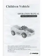
display. The OSD shows the Flight Mode, Speed and altitude, GPS status, 
distance to home and an arrow pointing home, time aloft, and voltage. A call 
sign is also available on the OSD, it is recommended to display your HAM call 
sign to satisfy amateur radio rules. 
The OSD is also helpful during prefl ight setup because it will tell the pilot the 
status of GPS systems. It will tell the pilot when the model has a suffi cient GPS 
lock and is ready to fl y. 

The video transmitter frequency and power output can be set directly from 
compatible Spektrum transmitters or set in the OSD menu.

OSD Menu

The OSD has a menu system which has options where the pilot can make 
changes. 
1. 

To enter the menu the motor must be disarmed. 

2. 

Flip the fl ight mode switch back and forth twice to enter the menu. 

3. 

To navigate the menu use elevator stick to move up and down through 
the menu, and aileron stick to move side to side through the menu.

Video System (BNF with FPV)

AutoLand

Opterra

10.9V

352

ft

4:27

685 ft

Initializing

MPH

18

AutoLand

Opterra

10.9V

352

ft

4:27

685 ft

Ready

MPH

18

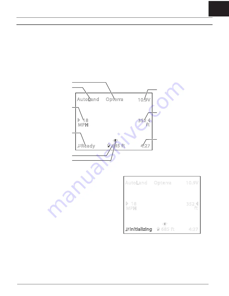
Flight Controller Status

When powering up the airplane to fl y, the OSD will display the fl ight status 
in the lower left corner. 
When fi rst powered on the OSD will show 

INITIALIZING

When the aircraft has a solid connection to the RC controller and a GPS 
lock, the OSD will display 

READY

The aircraft will not respond to controls until the status changes to

 Ready. 

To fl y without GPS features see the disabling GPS section of this manual. 

Callsign

On Screen Display

Flight Mode

Speed*

Flight controller status

Distance to home

Direction to home

Voltage

Altitude

Flight time

*Speed is calculated from GPS information, 
therefore it is ground speed, not airspeed. 

Содержание Opterra

Страница 1: ...Instruction Manual Bedienungsanleitung Manuel d utilisation Manuale di Istruzioni SAFE Select Technology Optional Flight Envelope Protection Opterra 1 2m...

Страница 2: ...ch if not properly followed create the probability of property damage collateral damage and serious injury OR create a high probability of super cial injury CAUTION Procedures which if not properly fo...

Страница 3: ...lations and guidance on UAS usage visit knowbeforeyou y org To receive product updates special offers and more register your product online at www e iterc com Box Contents Table of Contents 47 in 1200...

Страница 4: ...med for operation speci cally in this aircraft The programming in this receiver cannot be changed by the user SAFE Plus Flight modes are selected using Channel 5 IMPORTANT A transmitter with a 2 posit...

Страница 5: ...ht battery to the ESC The ESC will produce a long tone followed by a series of additional short tones 5 The receiver LED will begin to ash rapidly 6 Power on the transmitter while holding the transmit...

Страница 6: ...ngs onto the wing tube 3 Press the wing panels together onto the fuselage until the wings click into place 4 Insert the vertical ns into the pockets on top of the fuselage until the ns click into plac...

Страница 7: ...y charged 2200mAh battery C all the way forward in the battery compartment as shown IMPORTANT Adjust the battery position for proper CG accordingly 5 Connect the battery to the ESC the ESC is now arme...

Страница 8: ...s before the rst ight or to correct the heading during auto landing if it varies signi cantly from the heading set during takeoff 1 Remove the propeller if it is installed or activate throttle cut 2 W...

Страница 9: ...the pilot can make changes 1 To enter the menu the motor must be disarmed 2 Flip the ight mode switch back and forth twice to enter the menu 3 To navigate the menu use elevator stick to move up and do...

Страница 10: ...ted on the diagram to show Channel and Band The buttons will not function when the video transmitter is plugged into the ight controller Access the frequency and power level options from the Spektrum...

Страница 11: ...ng propeller as these items could become entangled 2 Move the entire aircraft as shown and ensure the control surfaces move in the direction indicated in the graphic If the control surfaces do not res...

Страница 12: ...ed to the Manually Adjusting Trim section to set the trim mechanically Aircraft Drift Trim Required Elevator Elevator Trim Elevator Trim Aileron Aileron Trim Aileron Trim Flight Preparation Manually A...

Страница 13: ...d roll wing tips up and down angles are limited to help you keep the aircraft airborne Above approximately 50 feet 15m pitch and roll control are increased slightly At any time release both sticks to...

Страница 14: ...rtual Fence Large sets the virtual fence in a circle with a radius of approximately 820 ft 250m from the home location Air eld Virtual Fence sets the virtual fence to an area approximately 400m long x...

Страница 15: ...tual Fence mode is active only the ailerons will wag left and right Release the HP AL bind button You must then indicate where the ying side of the air eld is in relation to the home location The thro...

Страница 16: ...ky it is occupying when Loiter is activated The altitude and location of the loiter can be adjusted with ight controls while the aircraft is in this mode the model will resume Loiter Mode after contro...

Страница 17: ...re required when AutoLand is activated However stick inputs can be used at anytime during AutoLand to avoid an obstacle lengthen the landing or smooth the nal are on landing Aileron stick Use the aile...

Страница 18: ...fety 3 Remove the ight battery from the aircraft 4 Power off the transmitter 5 Recharge the ight battery 6 Inspect the airframe for loose or damaged parts 7 Repair or replace all damaged parts 8 Store...

Страница 19: ...e of Power Components WARNING Always disconnect the ight battery from the model before removing the propeller Disassembly 1 Remove the screw A and spinner B 2 Remove the 4 screws C holding the motor m...

Страница 20: ...up Propeller damaged or installed incorrectly Land immediately replace or install propeller correctly Aircraft is dif cult to launch in the wind Launching the aircraft down wind or into a cross wind A...

Страница 21: ...shows or model demonstrations unless l The aircraft control system and pilot skills have successfully demonstrated all maneuvers intended or anticipated prior to the speci c event m An inexperienced p...

Страница 22: ...ion to speak with a Product Support representative Inspection or Services If this Product needs to be inspected or serviced and is compliant in the country you live and use the Product in please use t...

Страница 23: ...ration is subject to the following two conditions 1 this device may not cause interference and 2 this device must accept any interference including interference that may cause undesired operation of t...

Страница 24: ...canaux AR636 AR636 ricevitore sportivo a 6 canali AS3X AS3X and Telemetry Equipped Receivers AS3X und Telemetrieempf nger R cepteurs avec AS3X et t l m trie Riceventi con AS3X e telemetria SPMAR7350...

Страница 25: ...rra B rstenloser Motor 1 2M Opterra Moteur Brushless 1 2M Opterra Motore Brushless 1 2M Opterra EFL11408 Prop Spinner 1 2 Opterra Prop Spinner 1 2 Opterra H lice C ne 1 2 Opterra Elica Ogiva 1 2 Opter...

Страница 26: ...azione AS3X Interfaccia audio SPMA3065 AS3X Programming Cable USB Interface Spektrum USB Interface AS3X Empf nger Programmierkabel C ble de programmation USB AS3X pour PC Cavo di programmazione AS3X I...

Страница 27: ...e SAFE logo Passport Prophet EC3 and the Horizon Hobby logo are trademarks or registered trademarks of Horizon Hobby LLC The Spektrum trademark is used with permission of Bachmann Industries Inc All o...

Отзывы: