background image

23

E-flite Leader 480 ARF Assembly Manual

  5. Use a hobby knife and #11 blade to remove 

the covering from the canopy. Test fit the pilot into 

the canopy. It may be necessary to lightly sand to 

opening to fit the pilot.

  6. Once satisfied with the fit, use medium CA to glue 

the pilot in the canopy. Apply the glue to the stiffeners 

to keep the pilot in the canopy.

Center of Gravity

Required parts

Assembled airframe

Required Tools and Adhesives

Felt-tipped pen 

Ruler

Phillips screwdriver: #2

Balancing stand (optional)

An important part of preparing the aircraft for flight is 

properly balancing the model.


CAUTION

Do not inadvertently skip this step or 

property damage and injury could occur.

  1. Assemble your model in preparation for flight, 

making sure the wing is on securely and the motor 

battery is installed as instructed in this manual.

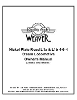
  2. The recommended Center of Gravity (CG) 

location for your model is 3

3

/

8

 to 3

3

/

4

 inches (85 

to 95mm) back from the leading edge of the wing 

as shown with the battery pack installed. Mark the 

location of the CG on the top of the wing with a 

felt-tipped pen.

  3. When balancing your model, support the plane 

inverted at the marks made on the top of the wing 

with your fingers or a commercially available 

balancing stand. This is the correct balance point 

for your model. Make sure your model is assembled 

and ready for flight before balancing.

Balancing Stand

Adjust the motor battery as necessary so the model is 

level or slightly nose down. This is the correct balance 

point for your model. You should find the CG to be 

very close with the battery installed as shown in this 

manual. Mark the location of the battery on the battery 

tray using a felt-tipped pen so it can be returned to this 

position if it is removed from your model.

After the first flights, the CG position can be adjusted 

for your personal preference.

Содержание Leader 480 ARF

Страница 1: ...Leader 480 ARF Assembly Manual...

Страница 2: ...r to operate correctly and avoid damage or serious injury Warnings Read and follow all instructions and safety precautions before use Improper use can result in fire serious injury and damage to prope...

Страница 3: ...are allowed Important Information Regarding Warranty Information Please read our Warranty and Liability Limitations section before building this product If you as the Purchaser or user are not prepare...

Страница 4: ...with 12 inch Wire and Jacks 16AWG EFLSP175 13 4 inch Aluminum Spinner with 4mm and 5mm Collets EFLA156 1 9 Civilian Pilot Blue with Glasses Required Tools and Adhesives Tools Equipment Box wrench 10m...

Страница 5: ...hinge and surrounding wood 2 Use a pin vise and 1 16 inch 1 5mm drill bit to drill a hole in the center of each hinge slot in the aileron to create a tunnel for the CA to wick into This will allow the...

Страница 6: ...sembled wing panel left and right Nylon control horn 2 6 inch 152mm servo extension 2 Micro screw lock connector 2 1mm x 180mm pushrod 2 Required Tools and Adhesives Side cutter Phillips screwdriver 0...

Страница 7: ...screw into each of the holes to cut threads in the surrounding wood Remove the screw before moving to the next step 8 Apply 2 3 drops of thin CA in each of the holes to harden the surrounding wood Thi...

Страница 8: ...the aileron in position when installing the linkage Remove the tape once the linkage has been installed 12 Repeat steps 1 through 11 to install the remaining aileron servo and pushrod Rudder and Elev...

Страница 9: ...eadlock on metal to metal fasteners to prevent them from vibrating loose 6 Prepare the rudder and elevator servo horns by enlarging the outermost hole in a long single sided elevator or long double si...

Страница 10: ...e tube will protrude from the fuselage by 1 32 inch 1mm use thin CA to glue the tube in the fuselage at the positions shown 2 Insert the Z bend of the pushrod wire into the nose gear steering arm as s...

Страница 11: ...wire Use side cutters to trim the excess pushrod wire 1 4 inch 6mm past the connector as shown When trimming the airplane to track straight on the ground the adjustment is made in the linkage for the...

Страница 12: ...cap screws four 3mm washers and four 3mm lock washers Use a 2 5mm hex wrench to tighten the screws Make sure to use threadlock on these screws as well to prevent them from vibrating loose 3 Place the...

Страница 13: ...ssembly can be placed on the motor shaft 2 Slide the cowling on the fuselage Place a piece of 3 32 inch 2 5mm thick two sided tape not included between the cowling and spinner backplate to set the spa...

Страница 14: ...3 drops of thin CA in each of the holes to harden the surrounding wood This will harden the threads so the screws do not easily strip the surrounding wood Prepare all four mounting holes at this time...

Страница 15: ...w before moving to the next step Prepare all four mounting holes at this time 2 Apply 2 3 drops of thin CA in each of the holes to harden the surrounding wood This will harden the threads so the screw...

Страница 16: ...ead cap screw 4 3mm washer 4 Required Tools and Adhesives Hex wrench 2 5mm 1 Slide the aluminum wing tube into the socket in the wing panel The tube will slide in easily so do not force it in any fart...

Страница 17: ...r poor alignment resulting in poor flight performance 2 Measure the distance from each stabilizer tip to the fuselage centerline to make sure the stabilizer is centered on the fuselage A A A A 3 Stand...

Страница 18: ...sing a paper towel and rubbing alcohol Do not use CA accelerator when gluing the stabilizer to the fuselage The CA must be allowed to soak into the fuselage and stabilizer for the best bond between th...

Страница 19: ...in to correct its alignment Align 90 degrees Do not use CA accelerator when gluing the fin to the fuselage The CA must be allowed to soak into the fuselage and fin for the best bond between the two su...

Страница 20: ...CA accelerator when gluing the hinges The CA must be allowed to soak into the hinge for the best bond between the hinge and surrounding wood 6 Once the CA has cured gently pull on the control surface...

Страница 21: ...throws Temporarily snap the backplate into position and mark the backplate along the bevel with a felt tipped pin Remove the backplate and use side cutters to trim the backplate Use sandpaper to sand...

Страница 22: ...opy Pilot optional Balsa stiffener 2 Required Tools and Adhesives Felt tipped pen Ruler Razor saw Medium CA Sanding block Medium grit sandpaper Hobby knife with 11 blade 1 Use a felt tipped pen to mar...

Страница 23: ...this manual 2 The recommended Center of Gravity CG location for your model is 33 8 to 33 4 inches 85 to 95mm back from the leading edge of the wing as shown with the battery pack installed Mark the lo...

Страница 24: ...atch your preferred style of flying Travel Adjust and Sub Trims are not listed and should be adjusted according to each individual model and preference Always install the control horns 90 degrees to t...

Страница 25: ...corrections to keep the airplane tracking straight down the runway and the Leader should gently break ground after a short takeoff roll and settle into a moderate climb angle Once at altitude set crui...

Страница 26: ...S NO WARRANTY OR REPRESENTATION EXPRESS OR IMPLIED ABOUT NON INFRINGEMENT MERCHANTABILITY OR FITNESS FOR A PARTICULAR PURPOSE OF THE PRODUCT THE PURCHASER ACKNOWLEDGES THAT THEY ALONE HAVE DETERMINED...

Страница 27: ...rranty conditions have been met your Product will be repaired or replaced free of charge Repair or replacement decisions are at the sole discretion of Horizon Non Warranty Repairs Should your repair n...

Страница 28: ...compliance with the AMA turbine regulations AMA Document 510 A 3 Model aircraft will not be flown in AMA sanctioned events air shows or model demonstrations unless a The aircraft control system and p...

Страница 29: ...uding the safety thong where applicable must have an inspection and pull test prior to flying 2 The pull test will be in accordance with the current Competition Regulations for the applicable model ai...

Страница 30: ...30 E flite Leader 480 ARF Assembly Manual Building and Flying Notes...

Страница 31: ...31 E flite Leader 480 ARF Assembly Manual Building and Flying Notes...

Страница 32: ...e fliterc com The Spektrum trademark is used with permission of Bachmann Industries Inc E flite DSM DSM2 and DSMX are trademarks or registered trademarks of Horizon Hobby Inc All other trademarks ser...

Отзывы: