5.
4
.3- ST Model
Installation
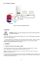
Figure 9. ST Device Installation Scheme
6- PACKAGE
-
The parts required for the installation of the device (wall bracket, 5 gaskets, 3 dowels, and fixing
screws for water connections) are placed in the upper styrofoam. The user manual is placed
between
the upper styrofoam and the combi boiler.
7- ASSEMBLY
CAUTION:
Warnings on the carton package must be observed during transportation
and storage of the device.
- The device is delivered in a carton box with dimensions of 735 x 345 x 490 (HxWxD) as
supported
by lower and upper styrofoams.
Boiler
Exit
CH Exit
CH Return
Boiler
Return
7.1- Selection of Device’s Assembly Location
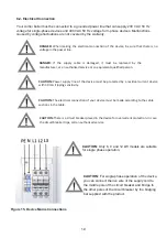
The location where the device can be assembled and spaces to be left around it for safety,
service, maintenance, and use purposes must be as shown in Figure 10.
Figure 10:
Indicates the minimum spaces to be left from the top and sides of the device
(Dimensions are given in mm).
For correct service and maintenance of the combi boiler, the installation should be carried out in
accordance with the following minimum spaces. The position of the combi boiler must be checked in
accordance with the technical rules.
15

