Rev. 01/11
-1.16-
TFXL-X
RATE PULSE OUTPUT CONNECTIONS
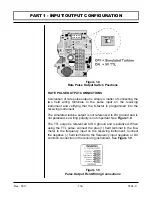
Connection of rate pulse output is simply a matter of connecting the
two field wiring terminals to the pulse input on the receiving
instrument and verifying that the K-factor is programmed into the
receiving instrument.
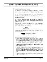
The simulated turbine output is not referenced to DC ground and is
not polarized, so wiring polarity is not important. See
Figure 1.9
.
The TTL output is referenced to DC ground and is polarized. When
using the TTL pulse, connect the plus (+) field terminal in the flow
meter to the frequency input on the receiving instrument. Connect
the negative (-) field terminal to the frequency input negative or DC
common connection in the receiving instrument. See
Figure 1.9
.
PART 1 - INPUT/OUTPUT CONFIGURATION
Figure 1.8
Rate Pulse Output Switch Positions
Figure 1.9
Pulse Output Field Wiring Connections
Содержание TFXL series
Страница 2: ......
Страница 10: ...Rev 01 11 1 8 TFXL X PART 1 TERMINOLOGY PC INTERFACE CABLE ...
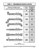
Страница 23: ...Rev 01 11 2 3 TFXL X PART 2 TRANSDUCER INSTALLATION Table 2 1 Straight Pipe Requirements ...
Страница 52: ......
Страница 53: ...APPENDIX ...
Страница 54: ......
Страница 55: ......
Страница 69: ......


