


24
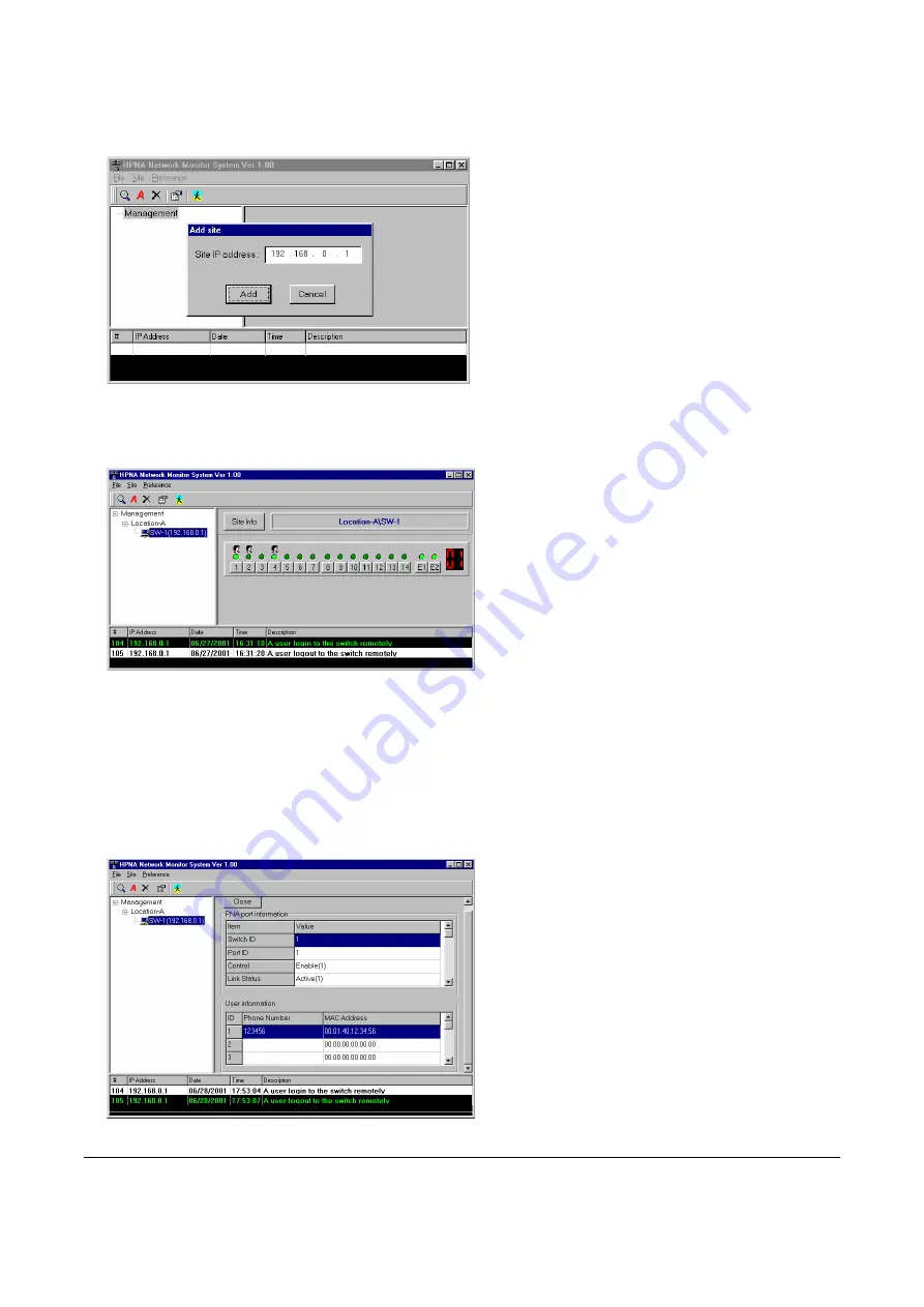
Choose ‘Site/Add’ function to add one switch system. For example, add site with IP address ‘192.168.0.1’ within
the ‘
TEST
’ domain. The SNMP utility will try to connect the switch when it is added. Then double click on ‘
SW-1
’
icon will retrieve the SNMP data for this SNMP monitor utility. As shows in the following figure,
The left side window in the above figure shows the connection topology -- there is only one switch ‘
SW-1
’ in the
selected system. The right side window displays the link status of each port -- Port1, Port4, PortE1 and PortE2
are link activated; Port1, Port2, and Port4 contain registered user info. The bottom window captures the events --
Trap number 104 and 105, Trap Source IP ‘192.168.0.1’, Trap Date, Trap Time, and Trap Description. To enable
this trap capturing function in SNMP utility, you need to open the destined Trap IP toward the SNMP utility in the
configuration utility ‘Property/SNMP’ window of ‘
SW-1
’, please refer Chapter 3, ‘Add Switch’ sub-section.
Click the button on each port in the above figure will list the detail information about current port. For example,
the following figure shows the button on Port1 has been pressed,


