


Dynamic Displays, Inc. User Manual Doc: 0048070
1625 Westgate Road 17C3 A/D Series Rev 2
Eau Claire, WI 54073 Glee 17C3 Page #13 of 26
OSD STRUCTURE
1.
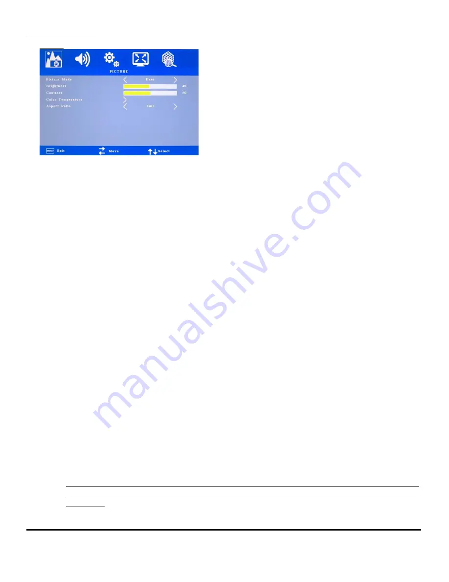
Picture
a.
Picture Mode (Picture Quality):
b.
Standard (Color: 50; Sharp 50; Tint 50)
i.
Soft (Color: 40; Sharp 50; Tint 50)
ii.
User (Color: 50; Sharp 50; Tint 50)
iii.
Vivid (Color: 50; Sharp 60; Tint 60)
c.
Brightness: Increases or decreases the brightness of the image.
d.
Contrast: Increases or decreases video gain of the image.
e.
Color:
Only Available on AV/Component Video
f.
Sharpness: Adjust picture sharpness.
Only Available on AV/Component Video
g.
Hue;
Only Available on AV/Component Video
h.
Color Temperature: Allows the user to adjust for desire White Color Balance to a predetermined
temperature colors or individual Red, Green and Blue Controls.
i.
Warm: Recall Warm Color Temperature from EEPROM (6500K).
ii.
Medium: Recall Medium Color Temperature from EEPROM (7500K).
iii.
Cool: Recall Cool Color Temperature from EEPROM (9300K).
iv.
User:
When selecting “USER” you may adjust each individual color one at a time
1.
Red: Allows the user to adjust the Red gain.
2.
Green: Allows the user to adjust the Green gain
3.
Blue: Allows the user to adjust the Blue gain.
i.
Aspect Ratio (The following aspect ratio descriptions are based on a landscape format):
Note: The aspect ratio of a monitor, is a proportional representation expressed as two distinct numbers
separated by a colon. In the case of monitors, the aspect ratio describes the correlation between width
and height.


