background image

Pilot Operating Handbook 
H3 Sport 135 HP


SECTION 7 

SYSTEMS 


Dynali_POH_H3 Sport 135 HP                       Rev. 3.3 – Issue date 15.01.2021                                                          Page 

64


7.2


ENGINE & ENGINE MOUNT  

The engine mount is made from stainless steel. It is mounted on two silentblocs which 
damp the vibrations throughout the airframe and is 

suspended on two rods which 

act as a clutch by lowering

 (tensioning the belts) 

or raising the engine

 (releasing 

the belts). When tensioned, the system is automatically locked (rods are on the other 
side of the tensioner axis). 
 
The 

Rotax 912ULS-I-BB 135HP

, supplies the most appropriate power to the helicopter 

thanks  to  the  ECU  electronically  controlling  the  injection  system  linked  to  bigger 
cylinders’  bore.  The  improvements  made  on  the  basic  engine  are  performed  within 
Dynali Sprl. The benefits of this version are the high torque and a comfortable power 
margin,  without  increasing  the  aircraft’s  weight.  Furthermore,  the  fuel  consumption 
stays  close  to  22  L/h.  Therefore,  it  is  the  solution  with  the  best  Power/Weight  and 
Power/Fuel consumption ratio. 


H3 Sport 

135 HP 


Engine 

Rotax 912ULS-I-BB 

Bore 

1600 cm

³


Specificity 

Injection M150 & big bore 

Cooling 

Water, oil and air 


NOTE 

 
The Rotax 900 series are among the best engines in the world. However, Rotax 
does not guarantee its engines when these are used in rotary wing aircraft. 

7.3


MAIN TRANSMISSION  

The drive pulley is bolted directly onto the engine shaft.  
 
Four V-belts transfer the movement to the receiving (driven) pulley which houses one 
freewheel. The freewheel is oil lubricated and can bear a torque of 660 Nm. It drives 
the rotor while the engine is running and keeps it free of movement when the engine 
is stopped or idle (failure or landing). 
 

Содержание H3 Sport 135 HP

Страница 1: ...Pilot Operating Handbook H3 Sport 135 HP SECTION 2 LIMITS IN USE Pilot Operating Handbook Dynali H3 Sport 135 HP Ultralight Helicopter Dynali_POH_H3 Sport 135 HP Revision 3 3 Issue date 15 01 2021 ...

Страница 2: ...Pilot Operating Handbook H3 Sport 135 HP SECTION 0 GENERAL Dynali_POH_H3 Sport 135 HP Rev 3 3 Issue date 15 01 2021 Page 2 Copyright by Dynali Helicopter Company Thines Belgium ...

Страница 3: ... Dynali SPRL registered in Belgium and other countries Other company and product names mentioned herein may be trademarks of their respective companies Mention of third party products is for informational purposes only and constitutes neither an endorsement nor a recommendation Dynali assumes no responsibility with regard to the performance or use of these products All understandings agreements or...

Страница 4: ...ION LOG SECTION Inserted by Rev N Date 1 Dynali SPRL 3 3 04 11 2020 2 Dynali SPRL 3 3 04 11 2020 3 Dynali SPRL 3 3 04 11 2020 4 Dynali SPRL 3 3 04 11 2020 5 Dynali SPRL 3 3 04 11 2020 6 Dynali SPRL 3 3 04 11 2020 7 Dynali SPRL 3 3 04 11 2020 8 Dynali SPRL 3 3 04 11 2020 9 Dynali SPRL 3 3 04 11 2020 10 Dynali SPRL 3 3 04 11 2020 ...

Страница 5: ...Serial N ___________________________________________________________ Registration ________________________________________________________ Type Certificate N ___________________________________________________ Aircraft builder and type certificate holder _________________________________________________ Distribution Partner ___________________________________________________ Owner ________________...

Страница 6: ...Pilot Operating Handbook H3 Sport 135 HP SECTION 0 GENERAL Dynali_POH_H3 Sport 135 HP Rev 3 3 Issue date 15 01 2021 Page 6 ...

Страница 7: ...9 LOAD FACTOR LIMITS 24 2 10 AUTHORISED OPERATION 24 2 11 NOISE LEVEL 25 2 12 STICKERS 25 2 13 DASHBOARD AND CONTROLS 27 2 13 1 MARKINGS 27 2 13 2 KEYPAD 29 2 13 3 CYCLIC CONTROL 32 SECTION 3 EMERGENCY PROCEDURES 34 3 1 ENGINE FAILURE AUTOROTATION 34 3 2 FORCED DITCHING 35 3 3 EMERGENCY EVACUATION 36 3 4 TAIL ROTOR OR TRANSMISSION FAILURE IN TRANSLATION 36 3 5 TAIL ROTOR OR TRANSMISSION FAILURE IN...

Страница 8: ...URE FOR WEIGHING THE HELICOPTER 58 6 3 CALCULATION OF WEIGHT AND BALANCE 58 6 4 WEIGHT SHEET 60 6 5 LATERAL BALANCE 61 SECTION 7 SYSTEMS 63 7 1 AIRFRAME UNDERCARRIAGE 63 7 2 ENGINE ENGINE MOUNT 64 7 3 MAIN TRANSMISSION 64 7 4 MAIN TRANSMISSION GEARBOX MTG 65 7 5 MAIN ROTOR 66 7 6 TAIL ROTOR 66 7 7 FLIGHT CONTROLS 67 7 8 RADIATORS 68 7 9 STABILISER 68 7 10 FUEL CIRCUIT 69 7 11 FLOATS 69 7 12 PARACH...

Страница 9: ...e condition for flight and for operation of the aircraft with in compliance with the procedures and limitations set out in this manual It is the owner s operator s responsibility to have this helicopter registered and insured according to country specific regulations The aircraft owner operator is also responsible for maintaining the helicopter in airworthy condition Maintenance instructions are p...

Страница 10: ...cesses for this helicopter by means of ground tests flight tests and detailed analysis 1 4 DEFINITION OF TERMS This manual uses WARNING CAUTION and NOTE in bold capital letters to indicate especially critical and important instructions Additionally the color of the panel red yellow and grey shading highlights the significance of the instruction Definitions for each term are given below WARNING A w...

Страница 11: ...Pilot Operating Handbook H3 Sport 135 HP SECTION 1 GENERAL Dynali_POH_H3 Sport 135 HP Rev 3 3 Issue date 15 01 2021 Page 11 1 5 3 VIEW DRAWING OF THE H3 SPORT ...

Страница 12: ...carbon tail struts The tail rotor blades are formed in carbon and are controlled by push pull cables The cabin cell and the stabilizer are made from vacuum infused carbon fiber and the canopy is in Perspex 1 7 TECHNICAL CHARACTERISTICS GENERAL Fuselage length 6 00 m Maximum Length including main rotor 7 80 m Height 2 50 m Height on wheels 2 60 m Interior cabin width 1 30 m Width of undercarriage 1...

Страница 13: ...erating Handbook H3 Sport 135 HP SECTION 1 GENERAL Dynali_POH_H3 Sport 135 HP Rev 3 3 Issue date 15 01 2021 Page 13 Blade twisting 0 Blade weight 11 3 kg Blade tip speed at 100 of nominal configuration 690 km h ...

Страница 14: ... 1 Freewheel 6 6 kN 6 rollers Rear transmission and Rear Transmission Gearbox RTG Rear transmission Shaft Rear transmission gearbox RTG 90 conic spiral gearing Reduction ratio RTG 2 1 Reduction ratios Engine main transmission shaft 2 9 1 Engine engine gear 2 4 1 Engine main rotor 10 3 1 Tail rotor main rotor 7 3 1 ROTAX ENGINE CONFIGURATIONS 4 cylinder four stroke spark ignition engine with oppose...

Страница 15: ...coolant Glycol diluted at 50 Quantity 6 L maximum Engine oil Type Synthetic oil with anti friction additive for 4 stroke engine Capacity 4 L Recommended oils Motorcycle 10W50 Consumption 0 1 L h maximum Oil MTG Type Hypoid SAE 70 to 90 SWEPCO 201 Capacity 0 8 L Oil RTG Type Hypoid SAE 70 to 90 SWEPCO 201 Capacity 70 mL Oil in the free wheel Type Anti friction additive oil FUCHS RENOLIN MR30 VG100 ...

Страница 16: ... the helicopter must not be operated WARNING During the entire flight adequate rotor loading must be maintained Do not perform any manœuvres resulting in the sensation of feeling lightness or near weightlessness WARNING Smoking on board is strictly prohibited CAUTION This helicopter has been designed and tested for a safe design load at maximum gross weight Flying at high speed in turbulent air es...

Страница 17: ...erating Outside Air T for safe flight 40 C Maximum wind speed or gust intensity for safe flight 60 km h Maximum demonstrated crosswind component 30 km h 16kts Maximum tailwind component for take off and landing 30 km h 16kts Maximum demonstrated operating altitude 10 000 ft Slope landing 8 longitudinal 4 lateral WARNING Do not consider flying in the likelihood of severe weather Thunderstorms may d...

Страница 18: ...w Limited operating range maximum 5 minutes Green Normal operating range 2 4 SPEED LIMITATIONS Red zone 0 km h 85 km h Green zone 86 km h 130 km h Yellow zone 131 km h 164 km h Red zone VNE 165 km h NOTE The yellow zone of the air speed starts at 131 km h although the cruising speed of the H3 Sport is 140 km h This zone points out the speed limit where all the flight manoeuvres can be safely execu...

Страница 19: ...inds CAUTION Notice the first red zone located between 0 and 85 km h that shows the recommended flight profile during take off and landing Thus it is recommended to have a speed close to 85 km h when flying lower than 500 ft ASFC 2 5 ROTOR AND ENGINE SPEED LIMITATION Engine RPM Interior circle Red circle 1000 RPM 1500 RPM Yellow circle 1501 RPM 5300 RPM Green circle 5301 RPM 5800 RPM Yellow circle...

Страница 20: ...the aircraft If the color zones of your H3 are not the same as the ones from the Handbook you can ask for an update to Dynali or your retailer Battery voltage Minimum voltage 12 V Low voltage caution range 12 1 12 5 V Normal range 12 6 14 V High voltage caution range 14 1 15 4 V Maximum voltage 15 5 V NOTE Some versions of the engine are equipped with two batteries These are then identical and hav...

Страница 21: ...Pilot Operating Handbook H3 Sport 135 HP SECTION 2 LIMITS IN USE Dynali_POH_H3 Sport 135 HP Rev 3 3 Issue date 15 01 2021 Page 21 ...

Страница 22: ...n some fuels induce knock in the cylinders and can cause piston destruction instantly ROTOR RPM 500 501 515 516 565 566 575 576 ENGINE RPM 1500 1501 5300 5301 5800 5801 5900 5901 VOLTS 12 12 1 12 5 12 6 14 14 1 15 4 15 5 CH T 70 71 80 81 100 101 110 111 OIL T 50 51 70 71 120 121 130 131 OIL PRESS 1 1 1 1 8 1 9 5 5 1 6 9 7 MTG T 0 110 111 130 131 2 7 WEIGHT LIMITS Maximum take off weight at sea lev...

Страница 23: ...g empty weight optional additional equipment occupants fuel and luggage at take off The maximum value specified above must never be exceeded 2 8 CENTER OF GRAVITY C G LIMITS CAUTION The balance envelope is conditioned by the correct adjustment of the flight controls which allow for full travel The original settings must not be modified Longitudinal balance is limited between the extreme aft balanc...

Страница 24: ...bited 2 10 AUTHORISED OPERATION Only daytime VFR flight is approved Night time VFR or IFR flight is prohibited Low G manoeuvre is prohibited WARNING Any manoeuver resulting in a low G condition can result in a loss of control Always maintain adequate load on the rotor and avoid aggressive forward control input performed from level flight or following a pull up Aerobatic flight is prohibited NOTE M...

Страница 25: ...lower than 65 dB A NOTE In order to avoid noise levels higher than 65 dB at ground level a cruising flight has to be executed at minimum 493 ft above ground 2 12 STICKERS Cabin In view of pilot and passenger must be installed by the customer distributor depending on the applicable regulation SOLO PILOT IN LEFT SEAT VNE 165 KM H NIGHT VFR IFR LOW G ICING CONDITIONS AEROBATIC FLIGHT PROHIBITED Howev...

Страница 26: ...Pilot Operating Handbook H3 Sport 135 HP SECTION 2 LIMITS IN USE Dynali_POH_H3 Sport 135 HP Rev 3 3 Issue date 15 01 2021 Page 26 Exterior NO STEP NO PUSH USE ONLY 10W50 OIL FUEL SP98 UL91 ...

Страница 27: ...AND CONTROLS Refer to Dynali s MoTeC User Manual to learn about the pages of the EFIS installed in the Dynali H3 Sport 135 HP 2 13 1 MARKINGS MASTER KEY Enables the activation of functions when turned on the ON position Functions are disabled when the key is set on the OFF position for at least 5 seconds This prevents from any involuntary action ...

Страница 28: ...ON If try to start the engine while the first fuel pump is OFF GOV The indicator is orange if the governor is not active The indicator is flashing red if the governor is preactivated The indicator is blue if the governor is active CHIP Main BTP and Rear BTA Indicators are green if there is no chip in the transmission gearbox and red if some is detected FRAME Main and Engine The indicator is green ...

Страница 29: ...urrent Red faulty function START Press to start the engine green light FUEL 2 Show the functioning of the fuel pump 2 REFUEL optional This function enable to pump fuel from an external tank to refuel the helicopter It cannot be activated if the engine is running or the battery voltage is 12 V NOTE The pump allows for refuel the tank up to 55 L 75 L if equipped with the optional 80 L fuel tank Once...

Страница 30: ...g Handbook H3 Sport 135 HP SECTION 2 LIMITS IN USE Dynali_POH_H3 Sport 135 HP Rev 3 3 Issue date 15 01 2021 Page 30 Oil temperature 30 C Indicator is green when the rotor is engaged and orange during button pressure ...

Страница 31: ...of radiators fans by pressing it when the water temperature is 70 C and the engine is running Fans stop by themselves when temperature gets 70 C It is possible to activate the fans by pressing and maintaining the button while the engine is not running RADIO TRT This button allows to switch on the radio when the engine is not running LANDING LIGHT optional Simply pressing the button enables to turn...

Страница 32: ...inHg of the maximum power Vibrate slowly and tone if collective 5 and Toil 50 C Vibrate slowly and tone if collective 5 and Poil 2 bar Vibrate slowly if collective 2 and engine 520 RPM Vibrate rapidly if rotor 550 RPM 2 13 3 CYCLIC CONTROL TRIM optional Active if Master Key ON Joystick with four directions Up Down Left et Right START Pressure 1 sec to start do not press for longer than 15 seconds ...

Страница 33: ...H_H3 Sport 135 HP Rev 3 3 Issue date 15 01 2021 Page 33 GOV Pressure 1 sec to pre activate deactivate if throttle between 20 and 60 PAGE Press the button Up or Down to change the page on the EFIS FRQ Press Down to select a memory Press Up to change frequency PTT Push To Talk ...

Страница 34: ...e schedules operational procedures is essential The helicopter must always be flown with the risk of engine failure in mind and must not be flown over any large bodies of water where a forced landing cannot be safely executed 3 1 ENGINE FAILURE AUTOROTATION WARNING A loss of power may be caused by a failure of engine or transmission A change in the noise level a yawing movement or a loss of revolu...

Страница 35: ... h with 100 rotor RPM Ø Use collective to maintain rotor RPM Ø Select landing point facing into wind Ø Approaching the ground act on the cyclic stick to flare and reduce rate of descent WITHOUT RISING THE COLLECTIVE Ø At around 10 ft bring the machine to horizontal and raise the collective to halt the descent Ø Preferably land into the wind NOTE It is strongly recommended to practice emergency pro...

Страница 36: ...ncy evacuation procedures including Actions to be taken in the event of a forced landing Operation of the seat harness How to open the doors How to safely exit and move away from the aircraft 3 4 TAIL ROTOR OR TRANSMISSION FAILURE IN TRANSLATION Ø Sudden yaw to the left cannot be controlled with the right pedal if the airspeed is below 100 km h Above 100 km h the vertical stabilisers remain effici...

Страница 37: ... HIGH VEGETATION Ø Plan touch down and flare with minimum ground speed and minimum rate of descent Ø Plan the contact with a positive pitch attitude not horizontal Ø Shut down engine by switching magnetos OFF and master switch OFF 3 9 LOSS OF VISIBILITY In case of canopy misting open air vents and lateral sliding vents to ensure proper ventilation If the situation cannot be corrected or occurs sud...

Страница 38: ... no emergency procedure CHIP Rear Orange The indicator is ON when chip is detected in de RTG Ø Land soon no emergency procedure FRAME Main Red Orange The indicator is ON when there is a loss of pressure in the main frame Ø Land soon no emergency procedure FRAME Engine Red orange The indicator is ON when there is a loss of pressure in the engine support Ø Land soon no emergency procedure OIL P Red ...

Страница 39: ... 2 Operates if the fuel pump 1 has no power supply If orange Ø Land soon no emergency procedure If red Ø Land immediately Alarm Buzzer Light tone If collective 2 and rotor 520 RPM If collective 5 Toil 50 C and engine ON If collective 5 Poil 2 bar and engine ON If start with pump 1 under no power Ø Act to re establish normal parameters ...

Страница 40: ...ided in this Pilot Operating Handbook is mandatory for safe operation 4 1 PRE FLIGHT CHECKLIST All daily or pre flight check list items consist of visual checks and do not replace professional mechanical inspection and maintenance The following check list applies for the all versions of the H3 Sport with notations covering the engine variants Note that depending on optional equipment installed it ...

Страница 41: ...tion 2 skids and lateral cabin Ø Check that the wheels are removed or locked on the undercarriage Ø Check that the horizontal pitch rod under the chassis has sufficient clearance from the skids Ø Check for oil coolant or fuel leaks on and below the engine and transmissions Ø Check the condition of the skids no cracks no excessive wear NOTE Skids may have a slight bend in the centre section see SEC...

Страница 42: ...el to the belts Ø Check the shaft bearing Ø No deformation of the rubber coupling attachment the main transmission shaft has not moved to the rear Ø Check the absence of leak on the freewheel Ø Check the tightening rings pulley and shaft bearing Ø Check the water level in the water expansion tank Station 4 stabiliser Ø Check the attachment of the tail tube Station 5 tail rotor Ø Check for leaks an...

Страница 43: ... fill above 1 3 of the gauge Ø Check for fuel smell Station 7 main rotor Ø Remove the parking strap from rear facing rotor Ø Check the rotor blades along their full length leading and trailing edge Ø Check the attachment of the blade tips Ø Check the upper and lower surface of blades Ø Check the absence of any damage Ø Check the cleanliness NOTE The cleanliness of the rotor blades may have importa...

Страница 44: ...ITH LOWER STOP MAXIMUM MANIFOLD PRESSURE MAX______inHG ALTIMETER SET INSTRUMENTS CHECKED ALL SWITCHES OFF BREAKERS PUSHED IN THROTTLE IDLE DUAL CONTROLS ONLY IF INSTRUCTION FLIGHT 4 2 2 ENGINE START CHECKLIST MASTER KEY ON BATTERY 1 ON BATTERY 2 ON NOTE It is important to transfer the oil remaining in the engine to the oil tank Therefore first verify that the rotor is disengaged Then open the oil ...

Страница 45: ...RE NOTE The LED becomes green instantaneously if all conditions are fulfilled Toil 30 Poil 3 bar WAIT UNTIL TOIL 50 C CHECK CORRECT OPERATION OF THE FREEWHEEL BY INCREASING RPM TO 100 AND THEN REDUCING THROTTLE NOTE The engine and rotor RPMs should desynchronize on the EFIS the freewheel must be smooth and noise free the rotor decelerates at its own rhythm CHECK IGNITION BY INCREASING ENGINE RPM T...

Страница 46: ... GOVERNOR FLASHING RED LIGHT INCREASE THROTTLE UP TO BETWEEN 20 AND 60 AND THEN PRESS THE GOV BUTTON 1 SECOND NOTE The position of the throttle is showed by a white arrow on the left part of the EFIS The white stripe on the scale represents the 20 60 zone See illustration TO ACTIVATE THE GOVERNOR BLUE LED MANUALLY BRING THE ENGINE RPM TO 100 NOTE To deactivate the governor it is also necessary to ...

Страница 47: ...TRUMENTS ALL GREEN CAUTION Perform take off into the wind and with least possible crosswind component TRANSITION INCREASE SPEED CONTROL TRAJECTORY SPEED MINIMUM 80 KM H BEFORE CLIMB WARNING The so called dead man s curve shown in the height speed diagram should be constantly kept in mind Both on takeoff and landing the areas indicated in the diagram should be avoided 4 2 4 LANDING CHECKLIST WIND D...

Страница 48: ...Pilot Operating Handbook H3 Sport 135 HP SECTION 4 NORMAL PROC Dynali_POH_H3 Sport 135 HP Rev 3 3 Issue date 15 01 2021 Page 48 ...

Страница 49: ...g the collective When left free the wind may cause the rotor to swing over to head height The pilot should survey the aircraft s surroundings and hold the cyclic to prevent the rotor swinging over WARNING Mind the spinning rear rotor close to obstructions or persons A fast turning rotor is almost invisible Do not vacate the helicopter until rotor is at a complete stop It is mandatory to keep contr...

Страница 50: ...Pilot Operating Handbook H3 Sport 135 HP SECTION 4 NORMAL PROC Dynali_POH_H3 Sport 135 HP Rev 3 3 Issue date 15 01 2021 Page 50 ...

Страница 51: ...vation increased temperature and or low air pressure will have a negative effect on performance 5 1 GENERAL WARNING Always keep at least 1 inHG MAP in relation to atmospheric pressure NOTE Satisfactory engine cooling has been demonstrated at outside air temperatures up to 35 C If needed for hotter climates an additional oil radiator can be installed The owner operator must remain within the normal...

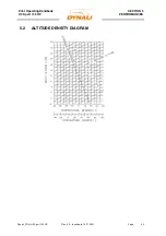
Страница 52: ...Pilot Operating Handbook H3 Sport 135 HP SECTION 5 PERFORMANCES Dynali_POH_H3 Sport 135 HP Rev 3 3 Issue date 15 01 2021 Page 52 5 2 ALTITUDE DENSITY DIAGRAM ...

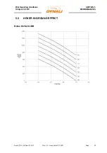
Страница 53: ...Pilot Operating Handbook H3 Sport 135 HP SECTION 5 PERFORMANCES Dynali_POH_H3 Sport 135 HP Rev 3 3 Issue date 15 01 2021 Page 53 5 3 HOVER IN GROUND EFFECT Rotax 912ULS I BB ...

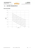
Страница 54: ...Pilot Operating Handbook H3 Sport 135 HP SECTION 5 PERFORMANCES Dynali_POH_H3 Sport 135 HP Rev 3 3 Issue date 15 01 2021 Page 54 5 4 OUTSIDE GROUND EFFECT Rotax 912ULS I BB ...

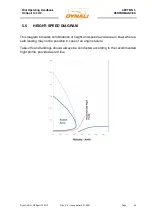
Страница 55: ...ate 15 01 2021 Page 55 5 5 HEIGHT SPEED DIAGRAM This diagram indicates combinations of height and speed avoid area in blue where a safe landing may not be possible in case of an engine failure Take offs and landings should always be conducted according to the recommended flight profile provided as red line ...

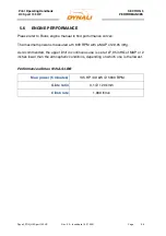
Страница 56: ...nual to find performance curves The maximum power is measured at 5 800 RPM with a MAP of 29 95 inHg As recommended the upper limit in continuous use is set at 27 95 inHG of MAP or 2 inches lower than the atmospheric conditions depending on which one is the lowest Performances Rotax 912ULS I BB Max power 5 minutes 135 HP 99 kW 5800 RPM Glide ratio 3 1 120 km h Climb rate 1 000 ft min ...

Страница 57: ... C G must be measured for each Dynali H3 Sport helicopter once assembly is completed The empty weight may not in any case except for options exceed the standard reference empty weight as indicated in this manual Maximum take off weight at sea level 500 kg Standard empty weight 312 5 kg Datum Rotor mast Forward balance limit in relation to datum 136 mm Aft balance limit in relation to datum 136 mm ...

Страница 58: ...ube until finding the equilibrium tail tube at 0 Ø Measure the distance between the tube under the skids and the rotor mast Ø Note the empty C G _________kg NOTE A positive distance means that the centre of gravity is located in front of the rotor mast A negative distance means that the centre of gravity is located at the rear of the rotor mast 6 3 CALCULATION OF WEIGHT AND BALANCE For each part o...

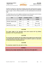
Страница 59: ...moment associated with the various parts of the helicopter and its payload ITEM WEIGHT KG DISTANCE DATUM MM MOMENT KG MM Standard empty weight 312 5 120 37 500 Passenger WPAX 606 WPAX x 606 Useable fuel 0 7 kg L WFUEL 170 WFUEL x 170 CAUTION The empty weight of the helicopter must never exceed 312 5 kg without parachute or 337 5 kg with parachute CAUTION The solo pilot must weigh at least 50 kg Be...

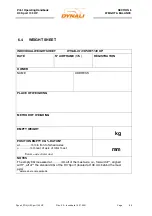
Страница 60: ... N AIRFRAME S N REGISTRATION OWNER NAME ADDRESS PLACE OF WEIGHING METHOD OF WEIGHING EMPTY WEIGHT kg POSITION EMPTY CG DATUM at mm in front of wheel axles mm rear of axis of rotor mast Datum axis of rotor mast mm NOTES The empty CG measured at mm aft of the mast axis i e forward of aligned with aft of the standard CG of the H3 Sport located at 136 mm behind the mast axis delete where not applicabl...

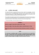
Страница 61: ...r is 13 kg more on the left hand seat so that the rotor mast is vertical in hover However the aircraft remains maneuverable well outside this level although listing This explains the obligation for the solo pilot to take the left hand seat WARNING Minimum weight of solo pilot in left hand seat 50 kg Maximum weight of solo pilot without ballast in right hand seat 125 kg When flying with two people ...

Страница 62: ...Pilot Operating Handbook H3 Sport 135 HP SECTION 6 WEIGHT BALANCE Dynali_POH_H3 Sport 135 HP Rev 3 3 Issue date 15 01 2021 Page 62 ...

Страница 63: ...ellent resistance to fatigue The airframe and engine mount are inflated up to bar to ensure the frames are leak tight Two light indicators located on the dashboard FRAME Main and FRAME Engine indicate a loss of pressure They light up when the pressure in the main frame FRAME Main or the engine support FRAME Engine is lower than 2 5 bar The possible leak can come either from the valve or in the wor...

Страница 64: ...rformed within Dynali Sprl The benefits of this version are the high torque and a comfortable power margin without increasing the aircraft s weight Furthermore the fuel consumption stays close to 22 L h Therefore it is the solution with the best Power Weight and Power Fuel consumption ratio H3 Sport 135 HP Engine Rotax 912ULS I BB Bore 1600 cm Specificity Injection M150 big bore Cooling Water oil ...

Страница 65: ...p this can cause premature wear of the freewheel Correct belt tensioning 15 kg for 1 cm deflection in the middle of the belt The transmission shaft transmits the movement forward to the main rotor via the main transmission gearbox and to the tail rotor via a rubber coupling joint and then to the rear transmission The long shaft which drives the tail rotor is supported by seven intermediate bearing...

Страница 66: ...n all weather conditions except for hail or icing conditions A mark is traced on the upper side of the blade to check for possible permanent elongation of the blades They are held by stainless steel sheets and aluminum blade roots Four stop bearings with oblique contact allow for the blade root to oscillate to set the pitch They are over dimensioned and can support excess speed up to 600 RPM These...

Страница 67: ... present any problem of wear A chip detector is also installed The left lateral bearing of the RTG even if fitted with a sealing ring may leak a little Regularly sponge the oil drop in the lip of this lateral bearing 7 7 FLIGHT CONTROLS Standard equipment includes dual controls The cyclic on the passenger side can be folded away The regulation only allows dual control during training flights with ...

Страница 68: ...7 8 RADIATORS The coolant radiator of the H3 is a very important item for training schools It is very large and allows for the H3 to be flown in hover flight for long periods without over heating without the requirement for periodic circuits to cool the engine oil Two oil radiators are positioned on top of the coolant radiator and provide the same high efficiency performance Four fans equipped wit...

Страница 69: ...filters are located between the tank and the pumps The two others the main filters are located after the fuel pumps The air vent of the fuel tank is provided by the breather line which also acts as an overflow spillage line This former end at a lower level than the engine components to avoid any spillage on them 7 11 FLOATS The Dynali H3 Sport can be equipped with dismountable floats These ultrape...

Страница 70: ...n the front allows for the canopy to stay open during boarding The locking mechanism can be operated from the Inside and outside by moving a steel locking device The door is properly locked when both latches are in upper position As an option two adjustable fresh air vents on each side are provided for ventilation The sliding window can be used as a photography opening and is large enough to pass ...

Страница 71: ...d inform the new owner operator of the manuals that he requires and suggest that he contact Dynali SPRL or the authorised distributor Furthermore the internet website www dynali com regularly shows new information made available to everybody Under the regulations the responsibility for the maintenance of an ultralight helicopter lies exclusively with the builder owner operator of the helicopter He...

Страница 72: ...may perform this after having followed a training course with an authorised distributor 3 Every 100h This operation must be performed in an authorised maintenance center by a qualified technician 4 Every 300h This operation must be performed in an authorised maintenance center by a qualified technician 5 Every 600h This operation must be performed in an authorised maintenance center by a qualified...

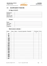
Страница 73: ...te 15 01 2021 Page 73 8 5 MAINTENANCE TRACKING H3 Sport 135 HP Registration Serial N Delivery date Observations Owner Name First name Address Telephone Maintenance calendar Hours Date Place Technical operation Remarks Technicia n Visa 25 50 75 100 125 150 175 200 225 250 275 300 325 350 375 400 425 450 etc ...

Страница 74: ...Pilot Operating Handbook H3 Sport 135 HP SECTION 8 MAINTENANCE Dynali_POH_H3 Sport 135 HP Rev 3 3 Issue date 15 01 2021 Page 74 8 6 SCHEDULED MAINTENANCE Refer to Maintenance Manuals H3 135 HP ...

Страница 75: ...ease study carefully the specific characteristics and the recommendations which follow 9 2 PILOT AIRMANSHIP Ø Keep both hands on the controls especially when close to the ground it is prohibited to release the controls Ø Be attentive at all times and beware of overconfidence Ø Never fly if you are not feeling in perfect shape In no case when you are influenced by alcohol lack of sleep or stress Ø ...

Страница 76: ...er margin is reduced A piston engine has little inertia With the slightest drop in engine speed the rotor will freewheel In icing conditions for example the engine may simply stop as compared with a fixed wing aircraft which will still be provided with thrust for a moment by its propeller The governor system may hide the early stages of icing Ø Keep up your speed and never remain hanging on your e...

Страница 77: ...licopter Be sure ground personnel or onlookers don t walk into the main rotor Mind the spinning rotor when hovering close to obstructions or persons It is advisable to maintain at least one rotor diameter distance from obstructions or persons when hovering with spinning rotor A fast turning rotor is almost invisible but may contain enough energy to kill a person Never let go of the control stick a...

Страница 78: ...senger increases the difficulty of managing the power 30 hours of solo flight is recommended for beginners and 5 hours for experienced pilots before carrying a passenger Beware of any stiffening in the controls Cyclic plate freezing or hardening of the grease on the mast Rapid complete blockage can occur in these cases In the pedals the grease hardens in the stop bearings of the rear rotor blades ...

Страница 79: ...nce i e the reactions developed flying airplanes For example in an airplane his reaction to an engine failure would be to immediately and considerably go forward with the stick In a helicopter application of inadequate forward stick could result in a low G situation or if the engine failure occurred during initial climb a reduction of rotor RPM combined with a high sink rate with the consequence o...

Страница 80: ...repared for the student who loses control and does the wrong thing Before allowing someone to touch the controls of the aircraft they must be thoroughly briefed concerning the sensitivity of the controls in a helicopter They must be firmly instructed to never make a large or sudden movement with the controls And the pilot in command must be prepared to instantly grip the controls should the studen...

Страница 81: ...ther noises he could hear In the engine reduction gear the damping system of instant torque claw is very noisy It is a noise like bumping or scrap The rear rotor siren sound comes from the 4 blades but also the gear of the RTG that resonates in the rear propeller shaft and the tail pipe At intermediate regimes or when the rotors are not driven the transmission belts are flapping causing a mechanic...

Страница 82: ... be repaired if damaged It must be replaced The angle between main transmission shaft main rotor mast and tail boom must be checked The skids must bend of maximum 17mm in the central section Check that the blade are not misaligned and that all the ball joint of the rotor head keep their movement free Check the free movement of the controls in all directions FLY SAFE ...

Страница 83: ...rk plugs oil etc d The Dynali warranty only applies insofar as i The products have been used according to the instructions in the current manuals in force at the time of the occurrence of the failure ii The servicing of the products have been implemented in compliance with the instructions contained in the service manual supplied with the products at the time of delivery as well as with any update...

Страница 84: ...li ii Abstain from causing any repair or technical intervention by any other person or organization other than Dynali or a Dynali approved distributor iii Make available to Dynali or an authorised Dynali representative at their registered address the defective part within 15 days of notification of the defect 3 It is understood that some adjustments may be necessary during the first hours in fligh...

Страница 85: ......
Отзывы: