background image


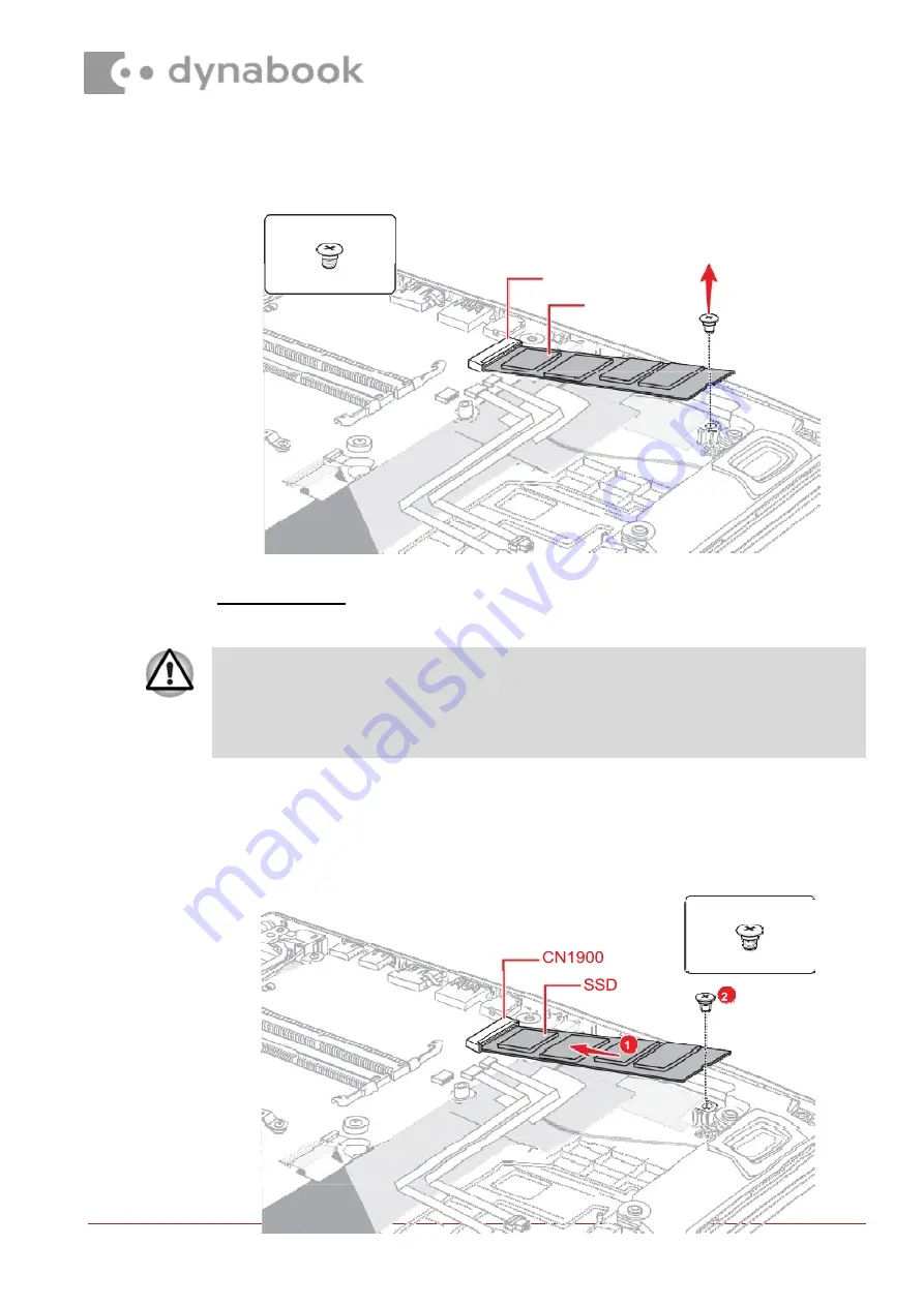
S2x3.5BT


S2x3.5BT


CN1900


SSD


To avoid damage, always hold the SSD only by its sides. 
To prevent the SSD from being distorted when installing the SSD pack into the 

computer, do not press the center of the SSD pack. Always hold the SSD pack by its 

sides. 


Figure 4-11 Removing the SSD


4.14.3 

Installing the SSD


To install the SSD, follow the steps below and refer to 

Figure 4-12


1.  Insert the 

SSD 

to the connector 

CN1900 

on the 

System 

Board (FMERSY*) 

slantwise. 

2.  Push down the 

SSD 

and secure it with the screw. 

Figure 4-12 Installing the SSD


Содержание SATELLITE PRO A50-J Series

Страница 1: ...ures of the Dynabook Maintenance Manual For your safety and the safety of the people around you it is important that you use Electrostatic Discharge ESD equipment Correctly utilizing of the equipment...

Страница 2: ...remove this component Once removed these components should be recycled as per local requirements To remove the battery the base assembly must be removed first 4 11 1 Removing the Cover Assembly and Ba...

Страница 3: ...cratch disassemble twist or bend the battery pack Figure 4 5 Removing the Base Assembly 2 4 12 1 Removing the Battery pack To remove the battery pack follow the steps below and refer to Figure 4 7 and...

Страница 4: ...ry pack in accordance with the laws and ordinances of your local authority CN8021 Battery Harness S2x4CT Figure 4 7 Releasing the battery pack 1 3 Disconnect the BATTERY HARNESS from the connector on...

Страница 5: ...he data loss or damage to the device S2x3 5BT CN1900 SSD 2 Removing the SSD To remove the SSD follow the steps below and refer to Figure 4 11 1 Remove the the following screw and disconnect the SSD fr...

Страница 6: ...re 4 22 Removing the Click pad 1 4 22 Figure 4 23 Removing the Click pad 2 4 22 Figure 4 24 Installing the Click pad 4 23 Figure 4 25 Removing the Speaker 1 4 24 Figure 4 26 Removing the Speaker 2 4 2...

Страница 7: ...ly follow the steps below and refer to Figure 4 4 to Figure 4 5 1 Close the display panel and turn the computer face down 2 Remove the following screws securing the Cover Assembly and the Base Assembl...

Страница 8: ...he Base Assembly 2 4 11 3 Installing the Base Assembly To install the Base Assembly follow the steps below and refer to Figure 4 4 to Figure 4 6 1 Set the Cover Assembly on the Base Assembly while sec...

Страница 9: ...en securing the Base Assembly be sure to drive the screws in the order of the number on Figure 4 4 2 Secure the Cover Assembly and Base Assembly with the screws 3 Turn the computer and open the displa...

Страница 10: ...T 4 12 Battery pack 4 12 1 Removing the Battery pack To remove the battery pack follow the steps below and refer to Figure 4 7 and Figure 4 8 1 Disconnect the BATTERY HARNESS from the connector CN8021...

Страница 11: ...attery s terminals visually If they are dirty wipe them clean with a dry cloth Figure 4 8 Releasing the battery pack 2 4 12 2 Installing the Battery pack To install the battery pack follow the steps b...

Страница 12: ...teps as detailed below 1 Open the left and right latches outside and remove the memory module s Figure 4 9 Removing the memory module s 1 Latches 2 Memory module 4 13 2 Installing the Memory module To...

Страница 13: ...ess on the top or bottom of a SSD Pressure may cause the data loss or damage to the device Figure 4 10 Seating the memory module 4 14 SSD 4 14 2 Removing the SSD To remove the SSD follow the steps bel...

Страница 14: ...puter do not press the center of the SSD pack Always hold the SSD pack by its sides Figure 4 11 Removing the SSD 4 14 3 Installing the SSD To install the SSD follow the steps below and refer to Figure...

Страница 15: ...er to Figure 4 13 to Figure 4 16 1 Disconnect the FPC FFC from the connector CN9600 on the SYSTEM board and CN9640 on the USB board Figure 4 13 Removing the Smart Card slot 1 2 Peel off the INSU CUSHI...

Страница 16: ...emove the Smart Card slot Figure 4 15 Removing the Smart Card slot 3 5 Disconnect the Smart Card FFC from the connector on the Smart Card slot Figure 4 16 Removing the Smart Card slot 4 4 15 2 Install...

Страница 17: ...ure it the with the screw 3 Connect the Smart Card FFC to the connector CN2170 on the system board 4 Stick the AL TAPE and INSU CUSHION SC in place 5 Connect the FPC FFC to the connector CN9600 on the...

Страница 18: ...ease the Wireless LAN antenna cable from the Cover Assembly 4 Remove the screw securing the Wireless LAN card 5 Disconnect the Wireless LAN card from the connector CN2630 on the System Board FMERSY Fi...

Страница 19: ...black cable to AUX or 1 and white cable to Main or 2 on the Wireless LAN card 4 Arrange the Wireless LAN antenna cables and stick the tape on the Cover Assembly 5 Stick a new INSU SQUARE in place...

Страница 20: ...e the following screw and disconnect the 3G MODULE from the connector CN2610 on the USB board FMERLT Figure 4 18 Removing the 3G module 4 17 2 Installing the 3G module To install the 3G module follow...

Страница 21: ...follow the steps below and refer to Figure 4 20 1 Disconnect the Fan harness from the connector CN3380 and CN3390 on the System Board FMERSY 2 Remove the following screws and the Fans from the Cover A...

Страница 22: ...er Assembly and secure them with the screws 2 Connect the Fan harness to the connector CN3380 and CN3390 on the System Board FMERSY 4 19 Fin 4 19 1 Removing the Fin To remove the Fin follow the steps...

Страница 23: ...t FFC from the connectors on the Click Pad and the connectors CN9510 and CN9550 on the System Board Figure 4 22 Removing the Click pad 1 2 Remove the square cushion and peel off the gasket tape from t...

Страница 24: ...k the square cushion 4 Connect the Click Pad FFC and Fingerprint FFC to the connector on the Click Pad and the connector CN9510 and CN9550 on the System Board 4 21 Speaker 4 21 1 Removing the Speaker...

Страница 25: ...2 Installing the Speaker To install the Speaker follow the steps below 1 Set the speakers to the Cover Assembly in place 2 Arrange the Speaker harness under the guides as shown below 3 Connect the Sp...

Страница 26: ...nstalling the Speaker 4 22 3G antennas 4 22 1 Removing the 3G antennas To remove the 3G antennas follow the steps below 1 Disconnect the SAR harness from the connector CN2650 on the USB board FMERLT 2...

Страница 27: ...ly Figure 4 29 Removing the 3G antennas 2 4 22 2 Installing the 3G antennas To install the 3G antennas follow the steps below and refer to Figure 4 28 to Figure 4 29 1 Stick new 3G antennas AUX Main i...

Страница 28: ...ng the system board do not handle with the handling prohibition area CN3270 CN3240 Keyboard Backlight Harness Keyboard FPC 4 23 System board 4 23 1 Removing the System board To remove the system board...

Страница 29: ...CN5930 CN8001 S2 x 4CT Figure 4 31 Removing the system board 2 3 Remove the following the screws Carefully lift up the system board Figure 4 32 Removing the system board 3...

Страница 30: ...o Figure 4 30 to Figure 4 33 1 Set the system board in place Figure 4 33 Installing the system board 2 Secure the system board with the screws 3 Connect the LCD Webcam harness to the connector CN5390...

Страница 31: ...4 24 2 Installing the DC IN jack To install the DC IN jack follow the steps below and refer to Figure 4 34 1 Set the DC IN jack to the slot on the Cover Assembly and arrange the DC IN jack harness to...

Страница 32: ...ecure it with the screws 2 Rotate the left display hinge to original position and secure it with two screws 4 26 Keyboard Cover Assembly The keyboard is assembled to the Cover Assembly by hot melt glu...

Страница 33: ...Keyboard Cover Assembly Figure 4 36 Removing the Keyboard Cover Assembly 4 26 2 Installing the Keyboard Cover Assembly To install the Keyboard Cover Assembly follow the step below and refer to Figure...

Страница 34: ...f GASKET on the cover assembly in place For LTE models Stick the one piece of AL Tape on the cover assembly in place For LTE models Stick two piece of D TAPE on the cover assembly in place and remove...

Страница 35: ...LCD unit follow the steps below and refer to Figure 4 37 to Figure 4 39 1 Detach the LCD mask from the top side of the LCD cover first Release the latches from the second one on the left as marked in...

Страница 36: ...the LCD mask by magnet Please be care not to lose it during removing the LCD mask Web Camera Shutter Figure 4 37 Removing the LCD unit 1 3 Remove the LCD mask 4 Release the LCD Webcam harness from the...

Страница 37: ...nit Be careful that the LCD Webcam harness is connected to the connector on the back of the LCD unit 7 Peel the pull tape and disconnect the LCD Webcam harness from the connector on the LCD unit Figur...

Страница 38: ...low the steps below 1 Connect the LCD Webcam harness to the connector on the LCD unit and secure it with the pull tape and glass tape 2 Peel off the separators on the bound detach tapes on the LCD cov...

Страница 39: ...Set the LCD unit in place 5 Arrange the LCD Webcam harness under the guides of the LCD cover Figure 4 41 Installing the LCD unit 2 6 Remove the separators on the top and bottom side of the LCD mask 7...

Страница 40: ...play hinges 4 28 1 Removing the display hinges To remove the display hinges follow the steps below and refer to Figure 4 44 1 Release the following screws and remove the left right hinges S2x2 5BT x2...

Страница 41: ...Figure 4 44 Removing the display hinges...

Страница 42: ...N antennas 4 29 1 Removing the Wireless LAN antennas To remove the Wireless LAN antennas follow the steps below 1 Release the Wireless LAN antenna cables from the guides on the LCD cover 2 Peel off th...
Страница 43: ...ra module To remove the camera module follow the steps below and refer to Figure 4 47 to Figure 4 48 1 Disconnect the camera FPC from the connector on the camera module and peel off the FPC from the L...

Страница 44: ...Camera Module Do not reuse the removed camera module Be sure to use new camera module Figure 4 48 Removing the camera module 2...

Страница 45: ...110 or G33C0009U110 4 30 2 Installing the Camera module To install the camera module follow the steps below and refer to Figure 4 47 to Figure 4 50 1 Peel off two protection sheets from the LCD cover...

Страница 46: ...111 For models with LCD module G33C000AE110 please use SQUARE CUSHION GM9044309211 Figure 4 49 Installing the Camera module 1 5 Arrange the LCD Webcam harness to the guides on the LCD cover 6 For some...

Страница 47: ...edding The following components contained within the AC adapter potentially contain hazardous substances and require special handling Printed Circuit Board 10 cm2 Capacitor 25 mm in height Photos of t...

Страница 48: ...Conventional type AC adapter AC Adapter with casing removed AC adapter printed circuit board AC adapter capacitor...

Отзывы: