background image

Appendix B   Board Layout 

Appendices


PORTÉGÉ X30W-J, dynabook V*/VZ*/VC* Series Maintenance Manual (960-941) [CONFIDENTIAL]


B-5 

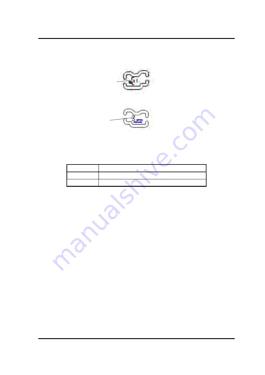
B.4  Lid board


(FDIALS*) View 


(Front) 


(Back) 


Figure B-4   Lid board (FDIALS*) layout 


Table B-4  Lid board (FDIALS*) connectors 


No. 

Name 

CN3291 

System board I/F connector 

IC3290 

Lid sensor 


IC3290 

CN3291 

Содержание PORTEGE X30W-J

Страница 1: ...NFIDENTIAL Dynabook Personal Computer PORT G X30W J dynabook V VZ VC Series Maintenance Manual Rev 00 Oct 2020 First issue Rev 01 Mar 2021 Addition of 5G LTE information Dynabook Inc File Number 960 9...

Страница 2: ...Any references in this Guide to TOSHIBA shall mean Dynabook Inc and or its affiliates Trademarks Intel Intel logo Thunderbolt Thunderbolt logo are trademark of Intel Corporation or its subsidiaries in...

Страница 3: ...f a hazard that could result in bodily injury if the safety instruction is not observed CAUTION Caution indicates the existence of a hazard that could result in property damage if the safety instructi...

Страница 4: ...how to diagnose and resolve FRU problems Chapter 3 Test and Diagnostics describes how to perform test and diagnostic operations for maintenance service Chapter 4 Replacement Procedures describes the r...

Страница 5: ...bol as it appears on the keyboard is printed in boldface type Key operation Some operations require you to simultaneously use two or more keys We identify such operations by the key top symbols separa...

Страница 6: ...Manual 960 941 Table of Contents Chapter 1 Hardware Overview 1 1 Features 1 1 1 2 SSD 1 9 1 3 Keyboard 1 12 1 4 TFT Color Display 1 15 1 5 Web camera 1 16 1 6 Power Supply 1 17 1 7 Batteries 1 18 1 8...

Страница 7: ...d Click pad Troubleshooting 2 24 2 9 Display LCD Touch panel Troubleshooting 2 26 2 10 Optical Disk Drive Troubleshooting Not used 2 28 2 11 LAN Troubleshooting Not used 2 29 2 12 Wireless LAN Bluetoo...

Страница 8: ...ogram 3 3 3 3 Entry of the DMI information 3 6 3 4 Heatrun Test 3 8 3 5 Main Test Menu 3 9 3 6 Memory Test 3 12 3 7 Hard disk SSD Test 3 13 3 8 Keyboard Test 3 16 3 9 LCD Panel Test 3 17 3 10 Battery...

Страница 9: ...D Card 4 14 4 4 BASE ASSY 4 15 4 5 BATTERY PACK 4 20 4 6 SPEAKER 4 23 4 7 5G LTE MODULE 4 27 4 8 5G LTE ANTENNA 4 33 4 9 FAN 4 40 4 10 SSD 4 42 4 11 HEAT SINK 4 44 4 12 SYSTEM BOARD 4 46 4 13 CLICK PA...

Страница 10: ...ppendix A Handling the LCD Module A 1 Appendix B Board Layout B 1 Appendix C Pin Assignments C 1 Appendix D Keyboard Matrix D 1 Appendix E Key Layout E 1 Appendix F Wiring Diagrams F 1 Appendix G BIOS...

Страница 11: ...Chapter 1 Hardware Overview...

Страница 12: ...1 Hardware Overview 1 ii CONFIDENTIAL PORT G X30W J dynabook V VZ VC Series Maintenance Manual 960 941...

Страница 13: ...TIAL 1 iii Chapter 1 Contents 1 1 Features 1 1 1 2 SSD 1 9 1 3 Keyboard 1 12 1 4 TFT Color Display 1 15 1 5 Web camera 1 16 1 6 Power Supply 1 17 1 7 Batteries 1 18 1 7 1 Main Battery 1 18 1 7 2 Batte...

Страница 14: ...1 15 Tables Table 1 1 M 2 PCIe SSD specifications 1 9 Table 1 2 Keyboard specifications 1 13 Table 1 3 LCD module specifications 1 15 Table 1 4 Web camera module specifications Front 1 16 Table 1 5 W...

Страница 15: ...960 941 CONFIDENTIAL 1 1 1 1 Features This model belongs to a convertible type PC and realizes 3 styles clamshell flat and tablet at use The following shows each unit position and system unit configur...

Страница 16: ...1 Hardware Overview 1 2 CONFIDENTIAL PORT G X30W J dynabook V VZ VC Series Maintenance Manual 960 941 Back view Left side Right side Figure 1 1 Appearance and each unit position 2...

Страница 17: ...1 Hardware Overview PORT G X30W J dynabook V VZ VC Series Maintenance Manual 960 941 CONFIDENTIAL 1 3 Underside Figure 1 1 Appearance and each unit position 3...

Страница 18: ...1 Hardware Overview 1 4 CONFIDENTIAL PORT G X30W J dynabook V VZ VC Series Maintenance Manual 960 941 Figure 1 2 Board connection diagram...

Страница 19: ...1 Hardware Overview PORT G X30W J dynabook V VZ VC Series Maintenance Manual 960 941 CONFIDENTIAL 1 5 Figure 1 3 System block diagram...

Страница 20: ...Tigerlake Core i5 1145G7 vPro 8MB 4 40GHz 4 8 Tigerlake Core i5 1135G7 8MB 4 20GHz 4 8 Memory Memory module in 16GB 32GB or 64GB size of LDDR4 4266 is mounted on the board SSD The computer is equipped...

Страница 21: ...keyboard The camera shutter is equipped on the front camera Some models support Face Recognition by Windows Hello Sound system The sound system is equipped with the following features Stereo speakers...

Страница 22: ...NFIDENTIAL PORT G X30W J dynabook V VZ VC Series Maintenance Manual 960 941 3D Acceleration sensor Finger print sensor on SecurePad BTO IR Camera Face Recognition Sensor BTO GPS for 5G LTE models BTO...

Страница 23: ...0CD120 G8BC000CD250 G8BC000CD510 Capacity 128GB 256GB 512GB Outline Width mm 22 00 0 15 Height mm 2 23 Max Length mm 80 0 0 15 Weight g 5 2 typ Data transfer speed Maximum Data Read Maximum Data Write...

Страница 24: ...mm 2 38 Max Length mm 80 0 0 15 Weight g 9 0g Max Data transfer speed Maximum Data Read Sequential Maximum Data Write Sequential 3 500MB s 2 200MB s 3 500MB s 2 900MB s 3 500MB s 3 000MB s Items Speci...

Страница 25: ...ions Maker Samsung Part code G8BC000CL120 G8BC000CL250 G8BC000CL510 Capacity 128GB 256GB 512GB Outline Width mm 22 00 0 15 Height mm 2 38 Max Length mm 80 0 0 15 Weight g 6 0g Max Data transfer speed...

Страница 26: ...oard is connected to the connector on the system board with the membrane and controlled by the keyboard controller The followings show the layout of the US keyboard and specifications of UK JP US keyb...

Страница 27: ...101 8 W x 3 8 0 2 H mm Weight 54 0 1 0g Key Pitch 19 mm X direction 18 mm Y direction mm keystroke 1 5 0 2 mm Number of keys 86 conformity with JIS 85 85 Backlight Yes White AccuPoint No Item Specific...

Страница 28: ...2 H mm Weight 54 0 1 0g Key Pitch 19 mm X direction 18 mm Y direction mm keystroke 1 5 0 2 mm Number of keys 86 conformity with JIS 85 85 Backlight Yes Red AccuPoint No Item Specifications Maker Tran...

Страница 29: ...source and can display a maximum of 16 77 million colors with 1 920x1 080 FHD resolutions Following shows a view of the LCD module and lists the specifications Figure 1 5 LCD module Table 1 3 LCD mod...

Страница 30: ...mounted on the web camera front Table 1 4 Web camera module specifications Front Item Specifications Chicony G9BC0006F110 G9BC0006E110 HD HD FA Camera Size mm Max 72 0 3 4 0 2 2 85 0 2 72 0 3 4 0 2 2...

Страница 31: ...that the DC power supply AC adapter is connected to the computer 2 Detects DC output and circuit malfunctions 3 Controls the battery icon and DC IN icon 4 Turns the battery charging system on and off...

Страница 32: ...the following table Table 1 6 Battery specifications Battery name Part code material Nominal voltage Capacity Main battery G71C000M7110 Lithium Ion 15 4 V 4Cell 53Wh G71C000M9110 Lithium Ion 15 4 V 4...

Страница 33: ...and power off The following table lists the charging time required for charges Table 1 7 Time required for charges Battery type Power on hours Power off hours Battery 4Cell 53Wh About 3 5 About 3 5 10...

Страница 34: ...pe C connector on the PC or to the USB Type C adapter It corresponds to USB PD The following table lists the AC adapter specifications Table 1 9 AC adapter specifications Item Specifications Maker Chi...

Страница 35: ...s pens and their specifications Table 1 10 Stylus pen specifications item Specifications Type Rechargeable Active Electrostatic AES stylus Rechargeable USB Type C Dongle pen cap is included Appearance...

Страница 36: ...h IC s F W setting Up to 4 096 level depends on touch IC s F W setting Returning time from sleep ms 100 50 msec 30 Shifting time to sleep Approximately 10 minutes Approximately 10 minutes Length mm 12...

Страница 37: ...es Use of non conforming battery could generate smoke or cause fire or rupture possibly resulting in serious injury Never allow caustic electrolyte fluid leaked from the battery to contact your eyes b...

Страница 38: ...ansion the PC functions a USB Type C adapters is prepared The following table shows the USB Type C adapter specifications Table 1 11 USB Type C adapter specifications Item Specifications Maker Goodway...

Страница 39: ...Chapter 2 Troubleshooting Procedures...

Страница 40: ...B Troubleshooting 2 19 2 5 1 Procedure 1 Reading check of data 2 19 2 5 2 Procedure 2 Replacement Check of USB unit 2 19 2 5 3 Procedure 3 Replacement Check of system board 2 20 2 6 SSD Troubleshootin...

Страница 41: ...5G LTE Troubleshooting 2 32 2 13 1 Procedure 1 Module Installation Check 2 32 2 13 2 Procedure 2 Antenna Connector Check 2 33 2 13 3 Procedure 3 Replacement Check 2 33 2 14 WiGig Troubleshooting Not u...

Страница 42: ...acement Check 2 43 2 19 HDMI port Troubleshooting 2 44 2 19 1 Procedure 1 Check on HDMI TV 2 44 2 19 2 Procedure 2 Connector Check and Replacement Check 2 45 2 20 USB Type C adapter Troubleshooting 2...

Страница 43: ...e unit in the field The FRUs covered are 1 Power supply 2 System Board 3 USB 4 M 2 SSD 5 Keyboard 6 Touch Pad Click Pad 7 Display LCD touch panel 8 Optical Disk Drive Not used 9 LAN Not used 10 Wirele...

Страница 44: ...r exchanging to a new board update also the EC KBC to the latest version by the test program or BIOS update For details refer to the Chapter 3 or Appendix G BIOS rewrite Procedures 3 After replacing t...

Страница 45: ...e for determining the troubleshooting procedures to execute Before going through the flowchart steps verify the following Ask him or her to enter the password if a password is registered Make sure tha...

Страница 46: ...error message displayed Is the startup logo displayed Is Windows OS loaded 1 Perform the Power Supply Troubleshooting Procedures in section 2 3 Perform the Power Supply Troubleshooting Procedures in s...

Страница 47: ...m each test Is an error detected during the test System can work without problem END Confirm on which test the error was detected and perform the appropriate procedures Yes No Does the touch pad click...

Страница 48: ...rocedures in Section 2 7 6 If an error is detected on the Touch Pad test perform the Touch Pad Click pad Troubleshooting Procedures in Section 2 8 7 If an error is detected on the LCD Panel test perfo...

Страница 49: ...leshooting Procedures in Section 2 17 16 If a malfunction is detected on the Web camera perform the Web Camera Troubleshooting Procedures in Section 2 18 17 If a malfunction is detected on the HDMI po...

Страница 50: ...ller controls many functions and components To determine if the power supply is functioning properly start with Procedure 1 and continue with the other Procedures as instructed The procedures describe...

Страница 51: ...er supply controller displays the power supply status with the DC IN Battery indicator as listed in the tables below Table 2 2 DC IN Battery indicator DC IN Battery indicator Power supply status White...

Страница 52: ...e C adapter is not used go to Procedure 3 Check 2 If any other devices except to the AC adapter are not connected to the USB Type C adapter go to Check 3 If any devices are connected remove all the de...

Страница 53: ...rocessor detects a malfunction the DC IN Battery indicator is flashing The blink pattern indicates an error as shown below Start Off for 2 seconds Error code 8 bit 1 On for one second 0 On for half se...

Страница 54: ...power supply 20h During power on sequence Waiting for PCNFEV signal assertion 1s timeout occurred Steady state output error at power on of E system power supply 21h At power on steady time PCNFEV sign...

Страница 55: ...ting for OPGOOD signal assertion occurred during power on sequence Other P system power supply On steady state output error 51h OPGOOD signal deasserted at power on steady state Other P system power s...

Страница 56: ...mpletely discharged Wait a few minutes to charge the battery pack while connecting the AC adapter to the computer If the battery pack is still not charged go to Check 2 Check 2 The battery s temperatu...

Страница 57: ...ttery pack may be disconnected Disassemble the computer and connect surely the battery pack to the system board If the problem still occurs perform Check 3 Check 3 Battery pack may be faulty Replace i...

Страница 58: ...Troubleshooting This section describes how to determine if the system board is malfunctioning or not Start with Procedure 1 and continue with the other procedures as instructed The procedures describe...

Страница 59: ...If any other error message other than below is displayed perform Check 2 a Date and Time reset to default Press F2 key to set Date and Time b Date and Time reset to default Press Windows button to set...

Страница 60: ...Procedure3 Replacement Check Perform the trouble shooting procedure for the device which doesn t pass the test program Refer to 2 5 USB Troubleshooting or later for details If the system board is faul...

Страница 61: ...unit condition with care for the followings 1 USB unit is not loosening 2 USB unit is connected straight to the connector 3 USB unit is connected fully in the connector 4 USB unit or connector is not...

Страница 62: ...Check of system board USB connectors are mounted on the system board directly So the system board may be faulty Disassemble the computer following the steps described in Chapter 4 Replacement Procedu...

Страница 63: ...the User s Manual 2 6 1 Procedure 1 Diagnostic Test Program Execution Check The test program for HDD SSD is stored in the Diagnostic Test Program Perform all of the items in the HDD SSD Test Refer to...

Страница 64: ...placement Check Check 1 The M 2 SSD may be damaged Replace it with a new one following the instructions in Chapter 4 Replacement Procedures and check the operation If the problem still exists perform...

Страница 65: ...tion function can be checked If an error occurs go to Procedure 2 If an error does not occur keyboard is functioning properly 2 7 2 Procedure 2 Connector Check and Replacement Check The connection bet...

Страница 66: ...h pad in Keyboard test of the Diagnostic Program Refer to Chapter 3 Tests and Diagnostics for more information If an error occurs go to Procedure 2 If an error does not occur Touch Pad is functioning...

Страница 67: ...3 Replacement Check Check 1 Touch Pad or the cable s may be faulty Replace them with new ones one by one following the steps in Chapter 4 Replacement Procedures If the problem still occurs perform Che...

Страница 68: ...1 Check on Windows OS This procedure checks if the touch screen is working properly by using the function of Windows Check 1 Make sure the mouse cursor is following your finger when you move your fing...

Страница 69: ...connectors on the display and the system board If the connection is loose reconnect it firmly If there is still an error go to Check 2 Check 2 The harness may be damaged Replace it with a new one and...

Страница 70: ...Drive function is not prepared So check if the Optical Disk Drive is working properly by using the function of Windows If any error is detected go to Procedure 2 2 10 2 Procedure 2 Connector Check and...

Страница 71: ...k 1 Make sure LAN cable is firmly connected to the LAN jack on the USB board LTE board If the problem still occurs perform Check 2 Check 2 LAN cable may be faulty Replace it with a new one If the prob...

Страница 72: ...apter 3 for more information about that If there is no problem Wireless LAN Bluetooth function should work properly If there is any error perform Procedure 2 2 12 2 Procedure 2 Connection Check The wi...

Страница 73: ...Refer to Chapter 4 Replacement Procedures for instructions on how to disassemble the computer and then perform the following checks Check 1 The antennas for wireless function may be faulty Replace the...

Страница 74: ...ps below starting with Procedure 1 and continuing with the other procedures as required Procedure 1 Module Installation Check Procedure 2 Antenna Connector Check Procedure 3 Replacement Check 2 13 1 P...

Страница 75: ...cted connector is wrong Connect the antenna cables correctly to the 5G LTE module Then perform Procedure 1 again If the problem still exists perform Check 3 Check 3 The connection between 5G LTE modul...

Страница 76: ...defective or damaged Replace it with a new one and perform Procedure 1 again If the problem still exists perform Check 2 Check 2 Antennas may be defective or damaged Replace them with new ones and per...

Страница 77: ...ure 1 Module Installation Check Check 1 This procedure checks if the WiGig module can be found on the Windows application Refer to Chapter 3 for more information about that If the computer has no prob...

Страница 78: ...e 1 If the problem still occurs go to the procedure 3 2 14 3 Procedure 3 Replacement Check WiGig module WiGig antenna or system board may be faulty Refer to Chapter 4 Replacement Procedures for instru...

Страница 79: ...r Check The connection of sound system is shown in the following figure As the connection may be defective check each connection first If headphone microphone or headset does not work properly reconne...

Страница 80: ...ight Left may be faulty Replace it with a new one following the steps in Chapter 4 Replacement Procedures If the problem still occurs perform Check 4 Check 3 The built in microphone on camera module o...

Страница 81: ...es automatically the micro SD Card and the data in the micro SD Card can be read If the card is not recognized or data are not read go to Procedure 2 2 16 2 Procedure 2 Connector Check and Replacement...

Страница 82: ...egister your fingerprint data for operation check clear the data after the check To clear it refer to the User s manual Procedure 1 Setting Windows sign in password Procedure 2 Registration of PIN and...

Страница 83: ...ter 2 Touch your registered finger on the fingerprint sensor and lift it When your fingerprint is authenticated you can sign in Windows If you fail this authentication continually five times you canno...

Страница 84: ...he following checks Check 1 The connection between Secure Pad and System board may be loose Make sure the cables are firmly connected to both the Secure pad and system board If the problem still occur...

Страница 85: ...ages perform Procedure 2 2 18 2 Procedure 2 Connector Check and Replacement Check The connection between the camera modules and the system board may be defective Otherwise they may be faulty Disassemb...

Страница 86: ...r Check and Replacement Check 2 19 1 Procedure 1 Check on HDMI TV Connect a HDMI compatible TV to the HDMI output port If the HDMI port works a desktop screen of Windows will appear on the TV display...

Страница 87: ...an error go to Check 2 Check 2 Check the setup condition of TV and returns to Procedure 1 As for the setting of the TV refer to the instructions manual for the TV If the problem still exists perform C...

Страница 88: ...as follows 1 Connect the power cord to the AC adapter USB PD type Then connect it to the USB Type C connector power delivery charging on the USB Type C adapter 2 Plug the power cord into a live wall...

Страница 89: ...n on the power of the external display 4 Plug the other end of the cable into the RGB port on the USB Type C adapter Switching the image output from computer s screen to the external display When you...

Страница 90: ...ck if the LAN is working properly by using the function of Windows How to connect the LAN cable is as follows 1 Connect the USB Type C adapter to the USB Type C connector on the computer 2 Turn off th...

Страница 91: ...3 Tests and Diagnostics PORT G X30W J dynabook V VZ VC Series Maintenance Manual 960 941 CONFIDENTIAL 3 i Chapter 3 Tests and Diagnostics...

Страница 92: ...3 Tests and Diagnostics 3 ii CONFIDENTIAL PORT G X30W J dynabook V VZ VC Series Maintenance Manual 960 941 3...

Страница 93: ...2 3 2 How to execute the test program 3 3 3 3 Entry of the DMI information 3 6 3 4 Heatrun Test 3 8 3 5 Main Test Menu 3 9 3 6 Memory Test 3 12 3 7 Hard disk SSD Test 3 13 3 8 Keyboard Test 3 16 3 9 L...

Страница 94: ...nd Diagnostics 3 iv CONFIDENTIAL PORT G X30W J dynabook V VZ VC Series Maintenance Manual 960 941 3 17 3 Start and Test procedure 3 36 3 17 4 Result 3 40 3 17 5 Log 3 41 3 17 6 How to terminate this t...

Страница 95: ...rmation The information about hardware such as HDD SSD memory and DMI is displayed If no DMI information is registered the message to request the DMI information registration is displayed 3 1 3 Check...

Страница 96: ...r maintenance USB Memory A Headphones and microphone Sound test 3 1 6 Setting of Battery Off mode Before returning to user set the Battery Off mode to the PC Check the Advanced System Configuration in...

Страница 97: ...this program executes the followings automatically NOTE If the test program doesn t start set Secure Boot to Disabled in Setup program As for Setup program refer to 3 18 SETUP Procedure 1 Check and u...

Страница 98: ...ay Does it update BIOS Vx xx Vx xx Y or N or press Enter Selection Y When the message above appears pressing ENTER will start BIOS update Then since the computer reboots automatically repeat from Step...

Страница 99: ...sh or a message may be displayed In that case turn on the power again and perform Procedure 3 or 4 The following message will appear If the PCB exchange or MDI information rewrite has been done press...

Страница 100: ...rmation of the current system board The information can be confirmed by the System Information screen displayed after start of test program or with DMI Entry utility After replacing the system board e...

Страница 101: ...CTL7AA21 Serial number e g 7G121732H Model Number e g PRT10N AAAA2 PCN BND Number e g PCN3384T0Z01FA1F XXX The meaning of buttons at the bottom is as follows Load DMI reads out the current DMI informa...

Страница 102: ...successively 1 Main Memory test 2 Sequential Read Test 3 V RAM Memory test To execute this test select 2 from the test program menu Top Menu and press Enter Explanation of each test 1 Main Memory test...

Страница 103: ...ogram under running temporarily press SHIFT Q After the stop pressing C continues the test and pressing E ends the test To return to the Top menu move the cursor to EXIT to TOP Menu on the screen abov...

Страница 104: ...pattern Test LCD brightness Test 5 Battery Charge Test 6 Fan Test 7 EXIT to TOP Menu After a subtest is selected the following message may appear The meaning of each item is as follows Test Loop Selec...

Страница 105: ...s to the screen to select Error Stop and Test Loop item selection Select No though any error occurs during the test the test is continued The setting of Yes No can be changed by pressing ENTER Go to T...

Страница 106: ...terns are 4 byte data 00000000h 55555555h AAAAAAAAh and FFFFFFFFh If empty area less than 3 byte length is found the test data is not written If the empty memory is 64MB or less this test is not execu...

Страница 107: ...the message HDD Read error and writes the information to the text file errorlog txt as an error log Subtest 2 Partial Read Test This test reads the data from the top and middle of the HDD area by 1GB...

Страница 108: ...is test displays the message HDD Write error and writes the information to the text file errorlog txt as an error log Subtest 4 Address Uniqueness Test This test writes the number of passes UNIT32 def...

Страница 109: ...BA the data length and test data for writing Dword is needed for this test Then this test writes the specified test data to the specified address and read them to compare If any errors occur at compar...

Страница 110: ...test displays the key code and scan code of a pressed key To back to the Keyboard test menu screen press Del Enter Displayed information Presses Key Code xx Presses Scan Code xx Subtest 2 Touch Pad T...

Страница 111: ...o the subtest you want to execute and press Enter Subtest 1 LCD Panel Test This test displays the following 4 colors Red Green Blue and Yellow from the left side of the display to right side from the...

Страница 112: ...test displays the letter H on the whole screen To back to the LCD Panel test menu screen press ENTER Subtest 4 LCD Brightness Test This test displays the white screen and changes the LCD brightness to...

Страница 113: ...ery Charge Test select 5 from the DIAGNOSTIC TEST Menu Main Test Menu press Enter and follow the directions on the screen When this test program is selected the following message appears The test star...

Страница 114: ...s if FANs work properly FAN1 Test FAN Low speed Target Low XXXX Rpm Result Low XXXX Rpm OK NG FAN High speed Target High XXXX Rpm Result High XXXX Rpm OK NG FAN2 Test FAN Low speed Target Low XXXX Rpm...

Страница 115: ...55555 RAM_001_12345678_1234_1000007812345678_00000000_55555555 T NAME Test name Test name example RAM_01 Main Memory Test HDD_01 Sequential Read Test HDD_02 Partial Read Test HDD_03 Address Jump Test...

Страница 116: ...13 1 Check of the wireless module Turn on the wireless communication function and check the module name via the application PC system information On this model a combo module which has both wireless...

Страница 117: ...function is available Click the icon If the computer can find any AP Access Point the network names like below will appear It shows the antenna cables are surely connected to the wireless module If t...

Страница 118: ...ce Manual 960 941 3 14 5G LTE Test Since there is no 5G LTE test in the test program for maintenance check if the 5G or LTE module is recognized by the PC on Windows Start the device manager If EMxxxx...

Страница 119: ...G X30W J dynabook V VZ VC Series Maintenance Manual 960 941 CONFIDENTIAL 3 25 3 15 Sound Test Since there is no sound test in the test program for maintenance check the functions related to sound on...

Страница 120: ...ersion AMT Setup Prompt 2 Language Security menu BIOS Password User Supervisor BIOS Access Rights 1 HDD SSD Password 2 User Master Bypass Mode at Restart 2 3 Secure Erase 1 2 Secure Boot 3rd party CA...

Страница 121: ...cution Technology 2 Power off and Charge System ON CDP Charge Mode USB Power in Off State USB Legacy Emulation System Configuration Wireless LAN Wireless WAN 2 Bluetooth Web Camera SD Host Controller...

Страница 122: ...ok V VZ VC Series Maintenance Manual 960 941 Boot menu Priority Boot Option 1 Boot Option 2 Boot Option 3 Boot Option 4 Priority for devices Add New Boot Option Exit menu Exit Saving Changes Exit Disc...

Страница 123: ...30W J dynabook V VZ VC Series Maintenance Manual 960 941 CONFIDENTIAL 3 29 3 16 2 Accessing to the SETUP Program Turn on the power while pressing F2 of the keyboard The following display appears Main...

Страница 124: ...3 Tests and Diagnostics 3 30 CONFIDENTIAL PORT G X30W J dynabook V VZ VC Series Maintenance Manual 960 941 Power Management menu screen Advanced menu screen...

Страница 125: ...3 Tests and Diagnostics PORT G X30W J dynabook V VZ VC Series Maintenance Manual 960 941 CONFIDENTIAL 3 31 Boot menu screen Exit menu screen...

Страница 126: ...ndow 1 Press F10 to accept the changes you made 2 To make other changes press N Repeat the steps above 3 To accept the changes press Y NOTE You can press Esc to quit at any time without saving changes...

Страница 127: ...iagnostics PORT G X30W J dynabook V VZ VC Series Maintenance Manual 960 941 CONFIDENTIAL 3 33 How to change setup Options Since a help is displayed on the right hand side of each menu screen refer it...

Страница 128: ...the following change is applied to the computer NOTE Before implementing this tool be sure to write the DMI information Replacing of System board FDIASY 3AXIS sensor board FDIASE and Lid board FDIALS...

Страница 129: ...agnostics PORT G X30W J dynabook V VZ VC Series Maintenance Manual 960 941 CONFIDENTIAL 3 35 3 17 2 Preparation Unzip the following file and copy all the contents to a USB memory Diamond10SensorCalibr...

Страница 130: ...step into the USB connector Procedure 3 Turn on the computer while pressing F12 to display the screen to select a boot device Procedure 4 Chose USB device on the selection screen and press Enter Then...

Страница 131: ...tically 1 Do not apply any vibration or shock to the PC 2 Keep the position specified in each Step for 2 to 3 seconds Gyro Calibration test Step 1 The side with the power button is X axis Set the PC a...

Страница 132: ...ibration test There are four steps in the Acceleration calibration test Step 1 Lay the PC as the display faces up Touch Setup OK button when the PC is ready When STEP 1 XXXXXX is displayed go to the n...

Страница 133: ...nance Manual 960 941 CONFIDENTIAL 3 39 Step 3 Rotate the PC 90 degrees counterclockwise slowly When STEP 3 XXXXXX is displayed go to the next step Step 4 Lay the PC as the display faces up When STEP 4...

Страница 134: ...dynabook V VZ VC Series Maintenance Manual 960 941 3 17 4 Result PASS If this test ends successfully PASS is displayed Tap OK button to back to the start screen FAIL If any problem occurred FAIL will...

Страница 135: ...e the log contents in an external memory device The log contents can t be saved in the internal disk to keep the user files 1 Touch Log Info to display the Log Information Display 2 Touch Save on Log...

Страница 136: ...3 Tests and Diagnostics 3 42 CONFIDENTIAL PORT G X30W J dynabook V VZ VC Series Maintenance Manual 960 941 Specify the output folder Output the log file...

Страница 137: ...3 Tests and Diagnostics PORT G X30W J dynabook V VZ VC Series Maintenance Manual 960 941 CONFIDENTIAL 3 43 3 17 6 How to terminate this tool Select Close on the tart screen The computer is powered off...

Страница 138: ...3 Tests and Diagnostics 3 44 CONFIDENTIAL PORT G X30W J dynabook V VZ VC Series Maintenance Manual 960 941...

Страница 139: ...Chapter 4 Replacement Procedures...

Страница 140: ...4 Replacement Procedures 4 ii CONFIDENTIAL PORT G X30W J dynabook V VZ VC Series Maintenance Manual 960 941...

Страница 141: ...Micro SD Card 4 14 4 4 BASE ASSY 4 15 4 5 BATTERY PACK 4 20 4 6 SPEAKER 4 23 4 7 5G LTE MODULE 4 27 4 8 5G LTE ANTENNA 4 33 4 9 FAN 4 40 4 10 SSD 4 42 4 11 HEAT SINK 4 44 4 12 SYSTEM BOARD 4 46 4 13 C...

Страница 142: ...ANTENNA 3 4 35 Figure 4 13 Removing the FAN 4 40 Figure 4 14 Removing the SSD 4 42 Figure 4 15 Removing the HEAT SINK 4 44 Figure 4 16 Removing the SYSTEM BOARD 1 4 48 Figure 4 17 Removing the SYSTEM...

Страница 143: ...ry to remove all the FRUs in order to replace one The chart below provides a guide as to which other FRUs must be removed before a particular FRU can be removed The numbers in the chart indicate the r...

Страница 144: ...tity Non 5G LTE LTE 5G 5G LTE ANTENNA MAIN ANTENNA 0 1 1 AUX ANTENNA 0 1 1 MIMO1 ANTENNA 0 0 1 MIMO2 ANTENNA 0 0 1 INSU SQUARE 111 0 3 3 ITEM Parts List ITEM No PART NAME Quantity Non 5G LTE LTE 5G SY...

Страница 145: ...1 GASKET R10 0 1 0 GASKET T10 0 1 0 61 INSU KB LOW 1 0 0 INSU KB LOW 5G 0 1 1 FIN CUSHION COV 2 2 2 INSU SQUARE 111 0 3 3 ITEM Parts List ITEM No PART NAME Quantity Non 5G LTE LTE 5G KEYBOARD 11 KEYBO...

Страница 146: ...A06 D TAPE TP SIDE R 1 1 1 A12 D TAPE TP LS R 1 1 1 A10 D TAPE TP LOW R 1 1 1 A13 D TAPE TP L CE 1 1 1 Parts which must not be reused are SQUARE CUSHION 351 CAUTION SEAL MAIN ANTENNA AUX ANTENNA MIMO...

Страница 147: ...T HEAD SCREW M2 5X4 PAN HEAD S02 M2 5 2 5C S THIN HEAD SCREW M2 5X2 5 FLAT HEAD S03 M2 2 3C S THIN HEAD SCREW M2X2 3 FLAT HEAD S04 M2 2 5 FLAT HEAD DANTUKI G SCREW M2X2 5SBNI S05 M1 2 1 1B S THIN HEAD...

Страница 148: ...when the computer is disconnected from an AC power source Remove any metal jewelry or accessories such as necklaces bracelets or rings in order to reduce the risk of electric shock Never work with wet...

Страница 149: ...ault 5 Do not perform any unnecessary work Always work in accordance with the disassembly and re assembly procedures in this manual 6 Keep parts removed from the computer in a safe place away from the...

Страница 150: ...th tags of the pressure plate such that the cable is fixed in the correct position Pull the cable to ensure that it is securely connected For spring connectors lift up the stopper frees the cable and...

Страница 151: ...ore fastening FRUs or other parts in place ensure that no cables are caught on screws or the FRU Check that all latches are securely closed When re assembling ensure that not to put the excessive powe...

Страница 152: ...ble and reassemble the computer One Philips screwdriver with type 00 bit for S THIN HEAD screws removing fixing the KEYBOARD One Philips screwdriver with type 0 bit for S THIN HEAD screws One Philips...

Страница 153: ...s or other damage if screws or components come loose NOTE Our company recommends that you use an electric screwdriver for quick and easy operations M1 2 1 2mm 0 0245 N m 0 25 kgf cm M2 2mm 0 167 N m 1...

Страница 154: ...e maintenance of the computer easier markings of the kinds of the screws including the types and lengths of the screws are indicated on the computer body Format Screw type Screw length mm Screw shape...

Страница 155: ...tation and to your operating system documentation for proper procedures and precautions 1 Insert a slender object about 0 8mm such as a straightened paper clip into the eject hole and pull the SIM car...

Страница 156: ...you remove the Micro SD card refer to the card s documentation and to your operating system documentation for proper procedures and precautions 3 Push the Micro SD card It will pop out partly so pull...

Страница 157: ...LTE ASSY non 5G LTE model M2 5 4B FLAT HEAD screw 4 Described as 4 in the Figure 4 3 M2 5 6B FLAT HEAD screw 8 Described as 6 in the Figure 4 3 5G LTE JP model M2 5 4B TORX HEAD screw 2 Described as 4...

Страница 158: ...placement Procedures 4 4 BASE ASSY 4 16 CONFIDENTIAL PORT G X30W J dynabook V VZ VC Series Maintenance Manual 960 941 non 5G LTE model Figure 4 3 Removing the BASE ASSY 1 BASE ASSY 6 6 4 4 6 6 6 6 6 4...

Страница 159: ...4 4 BASE ASSY 4 Replacement Procedures PORT G X30W J dynabook V VZ VC Series Maintenance Manual 960 941 CONFIDENTIAL 4 17 5G LTE model Figure 4 4 Removing the BASE ASSY 2 BASE LTE ASSY Rev 01...

Страница 160: ...tenance Manual 960 941 Installing the BASE ASSY To install the BASE ASSY or BASE LTE ASSY follow the steps below and refer to Figure 4 3 and 4 4 NOTE When replacing the BASE ASSY or BASE LTE ASSY with...

Страница 161: ...as 6 in the Figure 4 3 5G LTE JP model M2 5 4B TORX HEAD screw 2 Described as 4 in the Figure 4 4 M2 5 6B FLAT HEAD screw 8 Described as 6 in the Figure 4 4 5G LTE US UK model M2 5 4B FLAT HEAD screw...

Страница 162: ...N When handling the BATTERY PACK be careful not to short circuit the terminals Also do not drop hit apply impact scratch break twist or bend the BATTERY PACK 1 Peel off the INSU SQUARE 2 Disconnect th...

Страница 163: ...acement Procedures PORT G X30W J dynabook V VZ VC Series Maintenance Manual 960 941 CONFIDENTIAL 4 21 Figure 4 5 Removing the BATTERY PACK BATTERY PACK BATTERY HARNESS CN8021 M2x4C S THIN HEAD M2x4C S...

Страница 164: ...TTERY PACK is a lithium ion battery which can explode if not properly replaced used handled or disposed of For environmental reasons collect the spent BATTERY PACKs Use only batteries recommended by o...

Страница 165: ...ove the SPEAKER follow the steps below and refer to Figure 4 6 to 4 8 1 Disconnect the FP FFC finger print sensor model and CPAD FFC from the connectors on the CLICK PAD 2 Disconnect the FP FFC finger...

Страница 166: ...CONFIDENTIAL PORT G X30W J dynabook V VZ VC Series Maintenance Manual 960 941 3 Open the INSU KB LOW or INSU KB LOW 5G Figure 4 7 Removing the SPEAKER 2 INSU KB LOW 5G has another tab Open it together...

Страница 167: ...ce Manual 960 941 CONFIDENTIAL 4 25 4 Disconnect the SPEAKER HARNESS from the connector CN6290 on the SYSTEM BOARD 5 Remove the SPEAKER or SPEAKER 5G left and right from the slots of the COVER ASSY Fi...

Страница 168: ...SPEAKER 5G left and right to the slots of the COVER ASSY 2 Arrange the SPEAKER HARNESS in place and fix it with the INSU KB LOW or INSU KB LOW 5G 3 Connect the SPEAKER HARNESS to the connector CN6290...

Страница 169: ...ow the steps below and refer to Figure 4 9 1 Peel off the INSU SQUARE on the 5G MODULE or LTE MODULE 2 Disconnect the ANTENNA CABLEs 4 cables for 5G model 2 cables for LTE model from the connectors on...

Страница 170: ...941 5G MODULE LTE MODULE Figure 4 9 Removing the 5G LTE MODULE 5G MODULE or LTE MODULE 5G AUX ANTENNA Cable blue 5G MIMO2 ANTENNA Cable black 5G MIMO1 ANTENNA Cable white 5G MAIN ANTENNA Cable red M2...

Страница 171: ...ODULE NOTE Connect the cables according to the following order and steps 5G model AUX MIMO2 MIMO1 MAIN Detailed steps AUX MIMO2 MIMO1 MAIN Pass the AUX cable blue under the System board corner first T...

Страница 172: ...he MIMO1 cable white along to the MIMO2 cable black Stick the MIMO1 cable white to the INSU Make sure that the cables are not overlapped Do not pass the cable on the rib Connect the MAIN cable red to...

Страница 173: ...ue to the AUX connector on the LTE module Pass the AUX cable blue under the System board corner first Then hook it to the boss Stick the AUX cable blue to the INSU INSU Pass the MAIN cable red in the...

Страница 174: ...Z VC Series Maintenance Manual 960 941 3 Stick the INSU SQUARE to the 5G MODULE or LTE MODULE NOTE 5G model Stick the INSU SQUARE as shown below INSU SQUARE To the module edge To the module edge Fix t...

Страница 175: ...8 5G LTE ANTENNA Removing the 5G LTE ANTENNA To remove the 5G LTE ANTENNA follow the steps below and refer to Figure 4 10 to 4 12 1 Press the latch to the arrow direction to release 2 Pull up the GAS...

Страница 176: ...PORT G X30W J dynabook V VZ VC Series Maintenance Manual 960 941 4 Remove the 5G ANTENNA SPACERs and the INSU SQUAREs Turn up the INSU ANT HOLD NOTE Do not reuse the removed INSU SQUAREs Be sure to u...

Страница 177: ...Manual 960 941 CONFIDENTIAL 4 35 5 5G model Remove the MAIN ANTENNA AUX ANTENNA MIMO1 ANTENNA and MIMO2 ANTENNA LTE model Remove the MAIN ANTENNA and AUX ANTENNA NOTE Do not reuse the removed ANTENNA...

Страница 178: ...follow the steps below and refer to Figure 4 10 to 4 12 1 5G model Stick the MAIN ANTENNA AUX ANTENNA MIMO1 ANTENNA and MIMO2 ANTENNA to the COVER ASSY and arrange the cables in place LTE model Stick...

Страница 179: ...NA 4 Replacement Procedures PORT G X30W J dynabook V VZ VC Series Maintenance Manual 960 941 CONFIDENTIAL 4 37 NOTE Stick the ANTENNAs and arrange the cables according to the order and the steps below...

Страница 180: ...es Fix the cable with INSU SQUARE Do not pass on the PAD rib Pass the cable in the palm rest side Pass the AUX cable blue in the rib Fix the cable with INSU SQUARE Pass the cable in the palm rest side...

Страница 181: ...ce when replacing the following items ITEM Parts List ITEM No PART NAME Quantity Non 5G LTE LTE 5G 5G LTE ANTENNA MAIN ANTENNA 0 1 1 AUX ANTENNA 0 1 1 MIMO1 ANTENNA 0 0 1 MIMO2 ANTENNA 0 0 1 INSU SQUA...

Страница 182: ...rom the connector CN3380 on the SYSTEM BOARD 2 Remove the following screws and the FAN R M2 4C S THIN HEAD screw 2 3 Disconnect the FAN L HARNESS from the connector CN3390 on the SYSTEM BOARD 4 Remove...

Страница 183: ...low and refer to Figure 4 13 4 Set the FAN R to the COVER ASSY and secure it with the following screws M2 4C S THIN HEAD screw 2 3 Connect the FAN R HARNESS to the connector CN3380 on the SYSTEM BOARD...

Страница 184: ...the top or bottom of the SSD Pressure may cause data loss or damage to the device Removing the SSD To remove the SSD follow the steps below and refer to Figure 4 14 1 Remove the following screw and di...

Страница 185: ...es Maintenance Manual 960 941 CONFIDENTIAL 4 43 Installing the SSD To install the SSD follow the steps below and refer to Figure 4 14 1 Insert the SSD to the connector CN1900 on the SYSTEM BOARD 2 Sec...

Страница 186: ...INK To remove the HEAT SINK follow the steps below and refer to Figure 4 15 1 Remove the following screws and the HEAT SINK M2 2 3C S THIN HEAD screw 4 NOTE When removing the HEAT SINK be sure to remo...

Страница 187: ...ed to the CPU or HEAT SINK wipe them off with a cloth in advance 2 Apply new silicon grease Shin Etsu Chemical Co X 23 7921 5 on the CPU using a special syringe NOTE Apply new silicon grease as shown...

Страница 188: ...ogram Also update with the latest BIOS and EC KBC as described in Appendix G and in Appendix H 2 When replacing the SYSTEM board with a new one use the sensor calibration tool to adjust the sensors 3...

Страница 189: ...ANE and LID HARNESS from the connector CN3270 CN3260 and CN3290 on the SYSTEM BOARD 2 Turn up the INSUs and disconnect the CAMERA HARNESS from the connector CN9540 on the SYSTEM BOARD 3 Disconnect the...

Страница 190: ...ual 960 941 Figure 4 16 Removing the SYSTEM BOARD 1 INSU Lock bar LID HARNESS Connected to CN3290 LCD HARNESS Connected to CN5390 KB MEMBRANE Connected to CN3260 KB BL FPC Connected to CN3270 CAMERA H...

Страница 191: ...dures PORT G X30W J dynabook V VZ VC Series Maintenance Manual 960 941 CONFIDENTIAL 4 49 6 Remove the following screws and the SYSTEM BOARD M2 4C S THIN HEAD screw 2 Figure 4 17 Removing the SYSTEM BO...

Страница 192: ...941 Installing the SYSTEM BOARD To install the SYSTEM BOARD follow the steps below and refer to Figure 4 16 and 4 17 NOTE When replacing the SYSTEM BOARD with a new one stick the INSU SQUARE 321 COOL...

Страница 193: ...4 12 SYSTEM BOARD 4 Replacement Procedures PORT G X30W J dynabook V VZ VC Series Maintenance Manual 960 941 CONFIDENTIAL 4 51 INSU PCB SSD INSU PCB PIPE L INSU PCB PIPE R...

Страница 194: ...INSU KB LOW 5G in place before setting the SYSTEM BOARD Please note that INSU KB in the following pictures indicates INSU KB LOW or INSU KB LOW 5G 1 Set the SYSTEM BOARD to the COVER ASSY in place an...

Страница 195: ...re below 5 Connect the CAMERA HARNESS to the connector CN9540 on the SYSTEM BOARD 6 Close the INSU 7 Connect the KB BL FPC back light KB model KB MEMBRANE and LID HARNESS to the connector CN3270 CN326...

Страница 196: ...CK PAD To remove the CLICK PAD follow the steps below and refer to Figure 4 18 NOTE 5G model Remove MIMO2 ANTENNA first before removing the CLICK PAD 1 Peel off the AL TAPE 2 Peel off the CLICK PAD fr...

Страница 197: ...he CLICK PAD follow the steps below and refer to Figure 4 18 1 Stick a new CLICK PAD to the COVER ASSY 2 Turn over the COVER ASSY and stick a new AL TAPE in place NOTE 1 When replacing the CLICK PAD w...

Страница 198: ...J dynabook V VZ VC Series Maintenance Manual 960 941 Prepare required parts in advance when replacing the following items ITEM Parts List ITEM No PART NAME Quantity Non 5G LTE LTE 5G CLICK PAD CLICK P...

Страница 199: ...to Figure 4 19 and 4 20 1 Open the INSUs and release the W LAN ANTENNA CABLEs 2 Remove the following screw to remove the CORNER CAP R W LAN MAIN ANTENNA white cable M2 4C S THIN HEAD screw 1 3 Peel o...

Страница 200: ...the W LAN AUX ANTENNA CABLE black 5 Remove the following screw to remove the CORNER CAP L W LAN AUX ANTENNA black cable M2 4C S THIN HEAD screw 1 6 Peel off the W LAN AUX ANTENNA black cable from the...

Страница 201: ...he W LAN AUX ANTENNA black cable to the CORNER CAP L 2 Set the CORNER CAP L W LAN AUX ANTENNA black cable to the COVER ASSY and secure it with the following screw M2 4C S THIN HEAD screw 1 3 Stick the...

Страница 202: ...4 Replacement Procedures 4 14 W LAN ANTENNA 4 60 CONFIDENTIAL PORT G X30W J dynabook V VZ VC Series Maintenance Manual 960 941 NOTE Arrange the W LAN ANTENNA CABLEs as shown in the figure below...

Страница 203: ...4 14 W LAN ANTENNA 4 Replacement Procedures PORT G X30W J dynabook V VZ VC Series Maintenance Manual 960 941 CONFIDENTIAL 4 61...

Страница 204: ...0 941 4 15 LID BOARD Removing the LID BOARD To remove the LID BOARD follow the steps below and refer to Figure 4 21 1 Peel off the LID BOARD from the guides of the COVER ASSY 2 Disconnect the LID HARN...

Страница 205: ...TE When replacing the LID BOARD with a new one replace the D TAPE PCB LID on the LID BOARD with a new one in place 1 Connect the LID HARNESS to the connector CN3291 on the LID BOARD 2 Set the LID BOAR...

Страница 206: ...ntenance Manual 960 941 4 16 REAR CAMERA MODULE Removing the REAR CAMERA MODULE To remove the REAR CAMERA MODULE follow the steps below and refer to Figure 4 22 1 Open the INSU 2 Remove the REAR CAMER...

Страница 207: ...J dynabook V VZ VC Series Maintenance Manual 960 941 CONFIDENTIAL 4 65 Installing the REAR CAMERA MODULE To install the REAR CAMERA MODULE follow the steps below and refer to Figure 4 22 1 Set the RE...

Страница 208: ...ASSY COVER ASSY Removing the LCD FAT ASSY COVER ASSY To remove the LCD FAT ASSY COVER ASSY follow the steps below and refer to Figure 4 23 1 Remove the following screws and separate the LCD FAT ASSY...

Страница 209: ...ASSY to the COVER ASSY and secure it with the following screws M2 5 4B FLAT HEAD screw 3 Prepare the required parts in advance when replacing the following items ITEM Parts List ITEM No PART NAME Quan...

Страница 210: ...1 4 18 KEYBOARD Removing the KEYBOARD To remove the KEYBOARD follow the steps below and refer to Figure 4 24 and 4 25 1 Peel off the INSU KB LOW or INSU KB LOW 5G NOTE Do not reuse the removed INSU KB...

Страница 211: ...s Maintenance Manual 960 941 CONFIDENTIAL 4 69 2 Remove the following screw securing the KEYBOARD M1 2 1 1B S THIN HEAD screw 63 3 Remove the KEYBOARD NOTE The KEYBOARD is very thin so be careful of h...

Страница 212: ...ARD follow the steps below and refer to Figure 4 24 and 4 25 1 Set the KEYBOARD to the COVER ASSY in place and secure it with the following screws M1 2 1 1B S THIN HEAD screw 63 2 Stick a new INSU KB...

Страница 213: ...2 Stick the INSU KB LOW or INSU KB LOW 5G to the COVER ASSY as shown in the figure below Prepare the required parts in advance when replacing the following items ITEM Parts List ITEM No PART NAME Qua...

Страница 214: ...4 31 NOTE Handel with care of removing installing the LCD UNIT Refer to LCD unit_remove mp4 file for the details of removing the LCD UNIT 1 Release the latches and remove the LCD LOW CAP ASSY 2 Relea...

Страница 215: ...MODULE 4 Replacement Procedures PORT G X30W J dynabook V VZ VC Series Maintenance Manual 960 941 CONFIDENTIAL 4 73 NOTE Remove the HINGE CAP L ASSY LCD LOW CAP ASSY and HINGE CAP R ASSY as shown in t...

Страница 216: ...anual 960 941 3 Remove the following screws and the HINGE L R ASSY from the LCD COVER ASSY M2 5 2 5C S THIN HEAD screw 4 4 Release the LCD HARNESS and CAMERA HARNESS from the HINGE L R ASSY Figure 4 2...

Страница 217: ...TAPE TP LS R D TAPE TP LOW R and D TAPE TP SIDE R to the arrow pointing 6 Pull the D TAPE TP LS L D TAPE TP LOW L and D TAPE TP SIDE L to the arrow pointing 7 Pull the D TAPE TP L CE to the arrow poin...

Страница 218: ...4 Replacement Procedures 4 19 LCD CAMERA MODULE 4 76 CONFIDENTIAL PORT G X30W J dynabook V VZ VC Series Maintenance Manual 960 941...

Страница 219: ...4 19 LCD CAMERA MODULE 4 Replacement Procedures PORT G X30W J dynabook V VZ VC Series Maintenance Manual 960 941 CONFIDENTIAL 4 77...

Страница 220: ...DENTIAL PORT G X30W J dynabook V VZ VC Series Maintenance Manual 960 941 Figure 4 28 Removing the LCD 3 SHUTTER SWITCH LCD UNIT 3AXIS SENSOR BOARD D TAPE TP LS R D TAPE TP SIDE R D TAPE TP LOW R D TAP...

Страница 221: ...e lock bar and disconnect the LCD HARNESS from the connector on the LCD UNIT 13 Disconnect the TOUCH PANEL HARNESS from the connector on the TOUCH PANEL 14 Disconnect the SENSOR HARNESS from the conne...

Страница 222: ...t the CAMERA HARNESS FPC portion from the connector on the CAMERA MODULE 16 Remove the CAMERA COV ASSY from the LCD COVER ASSY 17 Remove the SHUTTER SWITCH from the CAMERA COV ASSY 18 Remove the CAMER...

Страница 223: ...ment Procedures PORT G X30W J dynabook V VZ VC Series Maintenance Manual 960 941 CONFIDENTIAL 4 81 19 Remove the CAMERA HARNESS FPC portion from the LCD COVER ASSY Figure 4 31 Removing the CAMERA MODU...

Страница 224: ...g the LCD CAMERA MODULE To install the LCD CAMERA MODULE follow the steps below and refer to Figure 4 26 to 4 31 NOTE When replacing the LCD COVER ASSY with a new one stick new D TAPE SEPA 201 211 D T...

Страница 225: ...AMERA HARNESS FPC portion to the connector on the CAMERA MODULE 3 Arrange the CAMERA HARNESS FPC portion to the LCD COVER ASSY in place 4 Set the SHUTTER SWITCH to the CAMERA COV ASSY 5 Set the CAMERA...

Страница 226: ...SHUTTER SWITCH moves properly and move it open position 14 Set the LCD LOW CAP ASSY to the LCD COVER ASSY while engaging the latches 15 Insert the LCD HARNESS into the HINGE L ASSY 16 Set the HINGE L...

Страница 227: ...INGE CAP R ASSY 1 1 1 INSU SQUARE 261 HD camera model 1 1 1 35 CU TAPE FA camera model 1 1 1 75 MAGNET 310 1 0 0 MAGNET 410 0 1 1 ITEM Parts List ITEM No PART NAME Quantity Non 5G LTE LTE 5G LCD UNIT...

Страница 228: ...4 Replacement Procedures 4 19 LCD CAMERA MODULE 4 86 CONFIDENTIAL PORT G X30W J dynabook V VZ VC Series Maintenance Manual 960 941...

Страница 229: ...CONFIDENTIAL Appendices...

Страница 230: ...Appendices App ii CONFIDENTIAL PORT G X30W J dynabook V VZ VC Series Maintenance Manual 960 941...

Страница 231: ...x Contents Appendix A Handling the LCD Module A 1 Appendix B Board Layout B 1 Appendix C Pin Assignments C 1 Appendix D Keyboard Matrix D 1 Appendix E Key Layout E 1 Appendix F Wiring Diagrams F 1 App...

Страница 232: ...Appendices App iv CONFIDENTIAL PORT G X30W J dynabook V VZ VC Series Maintenance Manual 960 941...

Страница 233: ...ecautions when handling the LCD module 1 When installing the LCD module in the LCD cover be sure to seat it so that it is properly aligned and maximum visibility of the display is maintained 2 Be care...

Страница 234: ...ll dirty try breathing on the surface to create a light condensate and wipe it again If the surface is very dirty we recommend a CRT cleaning agent Apply the agent to a cloth and then wipe the panel s...

Страница 235: ...941 CONFIDENTIAL A 3 5 Glass is used in the panel so be careful not to drop it or let it strike a hard object which could cause breakage or cracks 6 CMOS LSI circuits are used in the module so guard a...

Страница 236: ...941 7 Do not expose the module to direct sunlight or strong ultraviolet rays for long periods 8 Do not store the module at temperatures below specifications Cold can cause the liquid crystals to free...

Страница 237: ...nabook V VZ VC Series Maintenance Manual 960 941 CONFIDENTIAL A 5 10 If you transport the module do not use packing material that contains epoxy resin amine or silicon glue alcohol or oxide These mate...

Страница 238: ...Appendices Appendix A Handling the LCD Module A 6 CONFIDENTIAL PORT G X30W J dynabook V VZ VC Series Maintenance Manual 960 941...

Страница 239: ...rd FDIASE View B 4 B 4 Lid board FDIALS View B 5 Figure B 1 System board FDIASY layout Front B 1 Figure B 2 System board FDIASY layout Back B 2 Figure B 3 Sensor board FDIASE layout B 4 Figure B 4 Lid...

Страница 240: ...Appendix B Board Layout Appendices B ii CONFIDENTIAL PORT G X30W J dynabook V VZ VC Series Maintenance Manual 960 941...

Страница 241: ...ENTIAL B 1 B 1 System board FDIASY Front View Figure B 1 System board FDIASY layout Front Table B 1 System board FDIASY connectors and ICs Front No Name CN4800 USB Type C connector CN4821 USB Type C c...

Страница 242: ...X30W J dynabook V VZ VC Series Maintenance Manual 960 941 B 2 System board FDIASY Back View Figure B 2 System board FDIASY layout Back CN1900 CN3270 CN6290 CN8021 CN4850 CN3290 CN9540 CN5690 J6320 CN5...

Страница 243: ...y connector CN1900 SATA PCIe SSD I F connector CN3270 KB backlight I F connector CN3380 FAN 1 I F connector CN3390 FAN 2 I F connector CN3260 KB I F connector CN9550 Fingerprint sensor I F connector C...

Страница 244: ...J dynabook V VZ VC Series Maintenance Manual 960 941 B 3 3AXIS sensor board FDIASE View Front Back Figure B 3 Sensor board FDIASE layout Table B 3 Sensor board FDIASE connectors and ICs No Name IC335...

Страница 245: ...ynabook V VZ VC Series Maintenance Manual 960 941 CONFIDENTIAL B 5 B 4 Lid board FDIALS View Front Back Figure B 4 Lid board FDIALS layout Table B 4 Lid board FDIALS connectors No Name CN3291 System b...

Страница 246: ...Appendix B Board Layout Appendices B 6 CONFIDENTIAL PORT G X30W J dynabook V VZ VC Series Maintenance Manual 960 941...

Страница 247: ...connector 10 pin C 8 C 10 IS2220 SD card I F connector 13 pin C 8 C 11 CN9510 Click pad I F connector 10 pin C 9 C 12 CN9550 Fingerprint sensor I F connector 6 pin C 9 C 13 CN3260 KB I F connector 30...

Страница 248: ...rd I F connector 10 pin C 8 Table C 10 SD card I F connector 13 pin C 8 Table C 11 Click pad I F connector 10 pin C 9 Table C 12 Fingerprint sensor I F connector 6 pin C 9 Table C 13 KB I F connector...

Страница 249: ...F connector 31 pin Pin No Signal name Pin No Signal name 1 GND 18 XCSIBC E1P 2 MCMV2R8 P2V 19 XCSIBC E1N 3 MCMV2R8 P2V 20 GND 4 GND 21 ZCSIB1 E1P 5 GND 22 ZCSIB1 E1N 6 MCMA2R8 P2V 23 GND 7 GND 24 ZCS...

Страница 250: ...P1P 2 E3V 29 GND 3 ISHDA0 E3P 30 ZEDPA0 P1P 4 GND 31 ZEDPA0 P1N 5 ISHCL0 E3P 32 GND 6 PVT EF 33 ZEDPA1 P1P 7 PVT EF 34 ZEDPA1 P1N 8 PVT EF 35 GND 9 PVT EF 36 ZEDPA2 P1P 10 BKLPWM E3P 37 ZEDPA2 P1N 11...

Страница 251: ...Table C 3 Web camera FA I F connector 12 pin Pin No Signal name Pin No Signal name 1 P3V 8 GND 2 P3V 9 GND 3 P3V 10 ZUSBCF E3N 4 DMICIN P1P 11 ZUSBCF E3P 5 XDMCLK E1P 12 GND 6 CAMDET P3N 1T GND 7 GND...

Страница 252: ...GND 4 E3V 5 GND 6 3GON E1P 7 ZUSB3G E3P 8 GRFON E3P 9 ZUSB3G E3N 10 NC 11 GND 12 13 14 15 16 17 18 19 20 NC 21 NC 22 NC 23 NC 24 NC 25 3GSAR E1N 26 NC 27 GND 28 NC 29 ZU33GR E1N 30 UIMRS3G E3P 31 ZU33...

Страница 253: ...J dynabook V VZ VC Series Maintenance Manual 960 941 CONFIDENTIAL C 5 Table C 5 M 2 LTE I Fconnector 75 pin 2 2 Pin No Signal name Pin No Signal name 65 NC 66 UIMDT3G E3N 67 NC 68 NC 69 NC 70 E3V 71 3...

Страница 254: ...P 8 5GRFON E3P 9 ZUSB5G E3N 10 NC 11 GND 12 13 14 15 16 17 18 19 20 NC 21 NC 22 NC 23 5GWAKE E3N PEWAKE E3N 24 5G E3V 25 5GSAR E1N 26 NC 27 GND 28 IC2612 2 29 NC 30 IMRS5G E3P 31 NC 32 UIMCL5G E3P 33...

Страница 255: ...5GDET E3N 72 5G E3V 73 GND 74 5G E3V 75 NC 1T GND 2T GND C 7 CN3290 Lid board I F connector 3 pin Table C 7 Lid board I F connector 3 pin Pin No Signal name Pin No Signal name 1 S3V 2 PNLOFF S3N 3 GND...

Страница 256: ...W1 E3V UIMPW5G E3V UIMPW3G E3V 2 UIMRS5G E3P UIMRS3G E3P 3 UIMCL5G E3P UIMCL3G E3P 4 5 GND 6 NC 7 UIMIO5G E3P UIMIO3G E3P 8 9 GND 10 E3V UIMDT5G E3N UIMDT3G E3N 1T GND 2T GND 3T GND 4T GND 5T GND 6T G...

Страница 257: ...I F connector 10 pin Pin No Signal name Pin No Signal name 1 P3V 2 PDTINT P3N 3 GND 4 PDCLK P3P 5 GND 6 IPDDAT P3P 7 IC9560 4 8 I2CDT0 P3P 9 GND 10 I2CCK0 P3P 1T GND 2T GND C 12 CN9550 Fingerprint sen...

Страница 258: ...S3N 4 P5V 20 KBSC04 S3N 5 NC 21 KBSC06 S3N 6 KBRT06 S3N 22 KBSC08 S3N 7 KBRT02 S3N 23 KBSC10 S3N 8 KBRT03 S3N 24 KBSC01 S3N 9 KBRT05 S3N 25 KBSC11 S3N 10 KBRT01 S3N 26 KBSC07 S3N 11 KBRT04 S3N 27 KBS...

Страница 259: ...SCL S3P 8 ESDA S3P 9 BDET M5N 10 GND 11 IC8020 4 12 PVNVDC 13 PVNVDC 14 PVNVDC 15 PVNVDC 16 PVNVDC 17 PVNVDC PVNVDC 1T GND 2T GND C 16 CN3390 FAN 2 I F connector 4 pin Table C 16 FAN 2 I F connector 4...

Страница 260: ...ame Pin No Signal name 1 SLEEVE PXP 2 RING2 PXP 3 HEADR PXP 4 HEADL PXP 5 A GND 6 DETECT P3N C 19 CN5690 HDMI I F connector 19 pin Table C 19 HDMI I Fconnector 19 pin Pin No Signal name Pin No Signal...

Страница 261: ...ZUSBE1 E3N A8 ZP1SB2 EXP B8 ZP1SB1 EXP A9 PDVBUS1 B9 GND A10 ZSS0R0 E0N B10 ZSS0R1 E0N A11 ZSS0R0 E0P B11 ZSS0R1 E0P A12 GND B12 GND 1T GND 3T GND 2T GND 4T GND C 21 CN4821 USB Type C 2 I F connector...

Страница 262: ...4 pin Table C 22 Accelerometer Gyroscope 14 pin Pin No Signal name Pin No Signal name 1 E3V 2 E3V 3 E3V 4 ISHIN0 E3N 5 E3V 6 GND 7 GND 8 E3V 9 NC 10 NC 11 NC 12 E3V 13 ISHCL0 E3P 14 ISHDA0 E3P C 23 CN...

Страница 263: ...dynabook V VZ VC Series Maintenance Manual 960 941 CONFIDENTIAL C 15 Lid board FDIALS C 24 CN3291 System board I F connector 3 pin Table C 24 System board I F connector 3 pin Pin No Signal name Pin No...

Страница 264: ...Appendix C Pin Assignments Appendices C 16 CONFIDENTIAL PORT G X30W J dynabook V VZ VC Series Maintenance Manual 960 941...

Страница 265: ...abook V VZ VC Series Maintenance Manual 960 941 CONFIDENTIAL D i Appendix D Appendix D Keyboard Matrix D 1 Keyboard for UK D 1 D 2 Keyboard for US D 2 D 3 Keyboard for JP D 3 Figure D 1 UK Keyboard D...

Страница 266: ...Appendices Appendix D Keyboard Matrix D ii CONFIDENTIAL PORT G X30W J dynabook V VZ VC Series Maintenance Manual 960 941...

Страница 267: ...Appendix D Keyboard Matrix Appendices PORT G X30W J dynabook V VZ VC Series Maintenance Manual 960 941 CONFIDENTIAL D 1 D 1 Keyboard for UK Figure D 1 UK Keyboard...

Страница 268: ...Appendices Appendix D Keyboard Matrix D 2 CONFIDENTIAL PORT G X30W J dynabook V VZ VC Series Maintenance Manual 960 941 D 2 Keyboard for US Figure D 2 US Keyboard...

Страница 269: ...Appendix D Keyboard Matrix Appendices dynabook PORTEGE A30 E TECRA A30 G dynabook S Series Maintenance Manual 960 931 CONFIDENTIAL D 3 D 3 Keyboard for JP Figure D 3 JP Keyboard...

Страница 270: ...Appendices Appendix D Keyboard Matrix D 4 CONFIDENTIAL PORT G X30W J dynabook V VZ VC Series Maintenance Manual 960 941...

Страница 271: ...abook V VZ VC Series Maintenance Manual 960 941 CONFIDENTIAL E i Appendix E Appendix E Key Layout E 1 Keyboard for UK E 1 E 2 Keyboard for US E 1 E 3 Keyboard for JP E 2 Figure E 1 UK Keyboard E 1 Fig...

Страница 272: ...Appendices Appendix E Key Layout E ii CONFIDENTIAL PORT G X30W J dynabook V VZ VC Series Maintenance Manual 960 941...

Страница 273: ...Appendix E Key Layout Appendices PORT G X30W J dynabook V VZ VC Series Maintenance Manual 960 941 CONFIDENTIAL E 1 E 1 Keyboard for UK Figure E 1 UK Keyboard E 2 Keyboard for US Figure E 2 US Keyboard...

Страница 274: ...Appendices Appendix E Key Layout E 2 CONFIDENTIAL PORT G X30W J dynabook V VZ VC Series Maintenance Manual 960 941 E 3 Keyboard for JP Figure E 3 JP Keyboard...

Страница 275: ...0W J dynabook V VZ VC Series Maintenance Manual 960 941 CONFIDENTIAL F 1 Appendix F Wiring diagrams Not used F 1 RGB Monitor Loopback Connector Figure F 1 RGB Monitor Loopback Connector F 2 LAN Loopba...

Страница 276: ...Appendices Appendix F Wiring diagrams F 2 CONFIDENTIAL PORT G X30W J dynabook V VZ VC Series Maintenance Manual 960 941...

Страница 277: ...aining BIOS rewriting data 4 Turn on the power while holding down the tilde character key If the Japanese keyboard is installed hold down key instead of tilde key For example US Keyboard UK Keyboard K...

Страница 278: ...Appendices Appendix G BIOS rewrite procedures G 2 CONFIDENTIAL PORT G X30W J dynabook V VZ VC Series Maintenance Manual 960 941...

Страница 279: ...Z VC Series Maintenance Manual 960 941 CONFIDENTIAL H 1 Appendix H EC KBC Rewrite Procedures This Appendix explains how to rewrite the EC KBC system The EC KBC solely can t be updated It is updated at...

Страница 280: ...Appendices Appendix H EC KBC rewrite procedures H 2 CONFIDENTIAL PORT G X30W J dynabook V VZ VC Series Maintenance Manual 960 941...

Страница 281: ...Manual 960 941 CONFIDENTIAL I 1 Appendix I Reliability Appendix I Reliability The following tables show MTBF Mean Time between Failures in maximum configuration Table I 1 MTBF non 5G LTE model Time ho...

Страница 282: ...Appendices Appendix I Reliability I 2 CONFIDENTIAL PORT G X30W J dynabook V VZ VC Series Maintenance Manual 960 941...

Отзывы: