


The (+) and (-) power inputs are each protected by a 300 mA M (medium time-lag)
resettable fuse. If a shorting condition or polarity reversal occurs, the fuse will cut
power to the flow transducer circuit. Disconnect the power to the unit, remove the
faulty condition, and reconnect the power. The fuse will reset once the faulty
condition has been removed. DC Power cable length may not exceed 9.5 feet (3
meters).
Use of the GFM2 flow transducer in a manner other than that specified in this
manual or in writing from Dwyer, may impair the protection provided by the
equipment.
3. Principle of Operation
The stream of gas entering the Mass Flow transducer is split by shunting a small
portion of the flow through a capillary stainless steel sensor tube. The remainder of
the gas flows through the primary flow conduit. The geometry of the primary conduit
and the sensor tube are designed to ensure laminar flow in each branch.
According to principles of fluid dynamics the flow rates of a gas in the two laminar
flow conduits are proportional to one another. Therefore, the flow rates measured
in the sensor tube are directly proportional to the total flow through the transducer.
In order to sense the flow in the sensor tube, heat flux is introduced at two sections
of the sensor tube by means of precision wound heater-sensor coils. Heat is
transferred through the thin wall of the sensor tube to the gas flowing inside. As
gas flow takes place heat is carried by the gas stream from the upstream coil to
the downstream coil windings. The resultant temperature dependent resistance
differential is detected by the electronic control circuit. The measured temperature
gradient at the sensor windings is linearly proportional to the instantaneous rate
of flow taking place.
An output signal is generated that is a function of the amount of heat carried by
the gases to indicate mass-molecular based flow rates.
Additionally, the GFM2 Mass Flow Meter incorporates a precision analog
microcontroller and non-volatile memory that stores all hardware specific variables
and up to 10 different calibration tables. The flow rate can be displayed in 23
different volumetric or mass flow engineering units. Flow meter parameters and
functions can be programmed remotely via the RS-232/RS-485 interface or
optional Profibus DP interface. GFM2 flow meters support various functions
including: programmable flow totalizer, low, high or range flow alarm, automatic
zero adjustment (activated via local button or communication interface), 2
programmable SPDT relays output, 0 to 5 VDC / 4 to 20 mA analog outputs (jumper
selectable), self diagnostic alarm, 36 internal and user defined K-factor. Optional
local 2x16 LCD readout with adjustable back light provides flow rate and total
volume reading in currently selected engineering units and diagnostic events
indication.
SPECIFICATIONS
Service:
Clean gases compatible with wetted parts.
Wetted Materials:
GFM2-X-X-A: Anodized aluminum, brass, 316 SS fluoroelastomer O-rings;
GFM2-X-X-S: 316 SS, and fluoroelastomer O-rings; Buna-N, EPR and PTFE
O-rings optional.
Accuracy:
±1% FS.
Repeatability:
±0.25% FS.
Response Time:
2 seconds to within ±2% of actual flow.
Output Signal:
Linear 0 to 5 VDC (3000 Ω min. load impedance) and 4 to 20 mA
(500 Ω max. loop resistance).
Max. Particulate Size:
5 microns.
Temperature Limits:
32 to 122°F (0 to 50°C).
Power Supply:
11 to 26 VDC.
Process Connections:
1/8˝ compression fitting for flow rates ≤ 10 L/min; 1/4˝ for ≤
50 L/min; 3/8˝ for ≤ 100 L/min.
Display:
2 x 16 character LCD.
Pressure Limits:
500 psig (34.5 bar).
Leak Integrity:
1 x 10⁻⁹ smL/sec of helium.
Weight:
1.05 lb (0.48 kg).
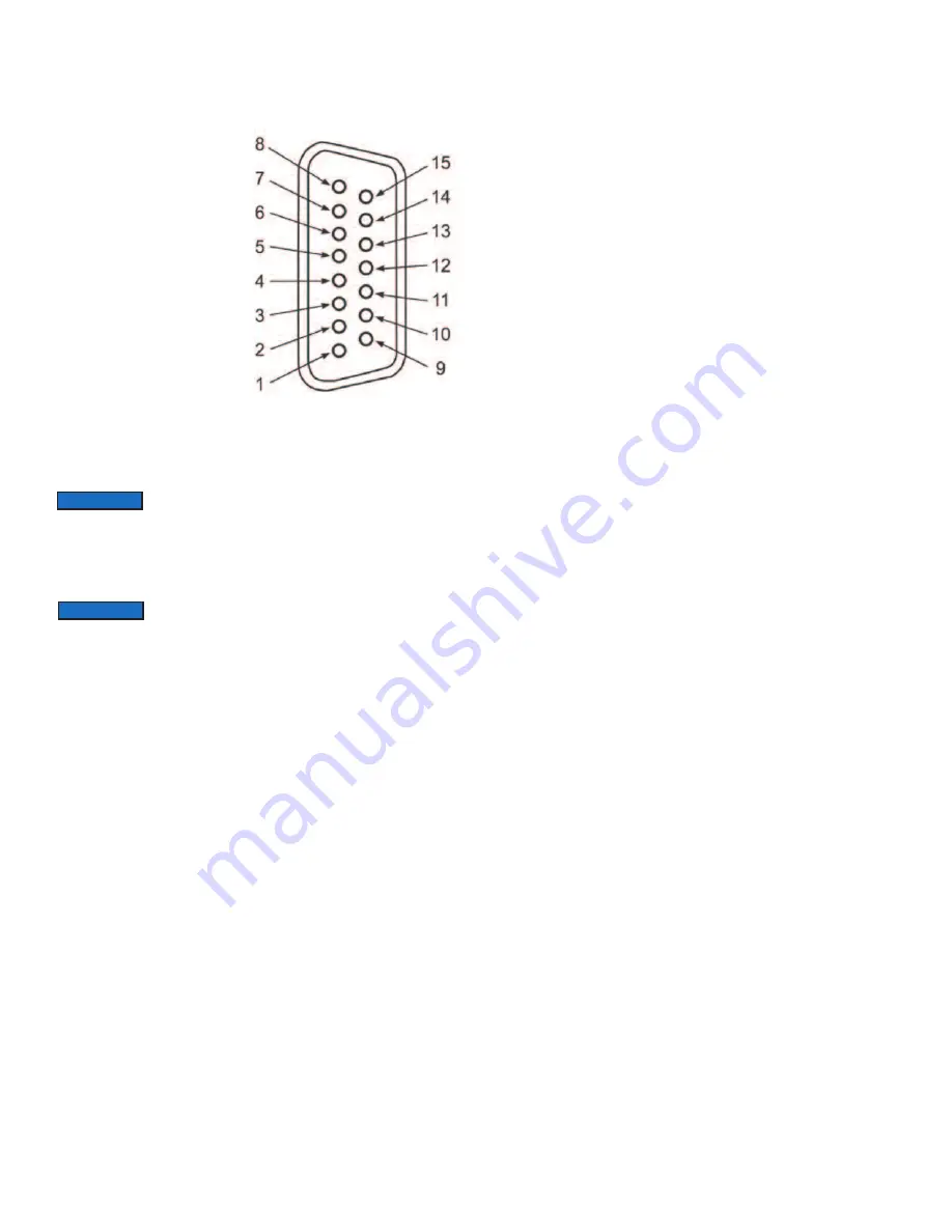
PIN GFM2 FUNCTION
1 Common, Signal Ground
For Pin 2 (4 to 20 mA return)
2 0 to 5 VDC or 4 to 20 mA
Flow Signal Output
3 Relay No. 2 - Normally Open
Contact
4 Relay No. 2 - Common
Contact
5 Common, Power Supply
(- DC power for 11 to 26 VDC)
6 Relay No. 1 - Common
Contact
7 Plus Power Supply
(+ DC power for 11 to 26 Vdc)
8 RS485 (-) (Optional RS232 TX)
9 RS232 Signal GND (RS-485
GND Optional)
10 Do not connect
(Test/Maintenance terminal)
11 Relay No. 2 - Normally Closed
Contact
12 Relay No. 1 - Normally Open
Contact
13 Relay No. 1 - Normally Closed
Contact
14 Do not connect
(Test/Maintenance terminal)
15 RS485 (+) (Optional RS232
RX) Shield Chassis Ground
In general, "D" Connector numbering patterns are
standardized. There are, however, some connectors with
nonconforming patterns and the numbering sequence on your mating
connector may or may not coincide with the numbering sequence shown in our
pin configuration table above. It is imperative that you match the appropriate wires
in accordance with the correct sequence regardless of then particular numbers
displayed on the mating connector.
NOTICE
Make sure power is OFF when connecting or disconnecting
any cables in the system.
NOTICE
Page 4