


UART Error Codes:
1 - Not Supported Command or Back Door is not enabled.
2 - Wrong # of Arguments.
3 - Address is Out of Range (MR or MW commands).
4 - Wrong # of the characters in the Argument.
5 - Attempt to Alter Write Protected Area in the EEPROM.
6 - Proper Command or Argument is not found.
7 - Wrong value of the Argument.
8 - Reserved.
9 - Manufacture specific info EE KEY (wrong key or key is disabled).
9. TROUBLESHOOTING
9.1 Common Conditions
Your GFM2 Digital Mass Flow Meter was thoroughly checked at numerous quality
control points during and after manufacturing and assembly operations. It was
calibrated according to your desired flow and pressure conditions for a given gas
or a mixture of gases.
It was carefully packed to prevent damage during shipment. Should you feel that
the instrument is not functioning properly, please check for the following common
conditions first:
Are all cables connected correctly? Are there any leaks in the installation? Is the
power supply correctly selected according to requirements? When several meters
are used a power supply with appropriate current rating should be selected.
Were the connector pinouts matched properly? When interchanging with other
manufacturers' equipment, cables and connectors must be carefully wired for
correct pin configurations. Is the pressure differential across the instrument
sufficient?
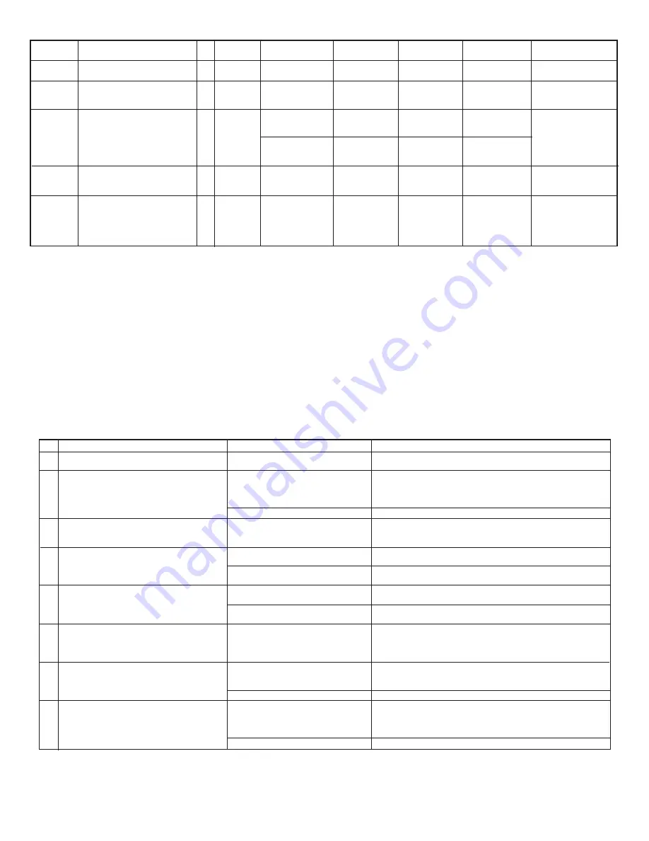
Command
Name
Maintenance
Timer
Full Scale
LCD Back
Light
Read
EEPROM
Memory
Write
EEPROM
Memory
Description
Hours since last time unit was
calibrated.
Returns the full scale rated flow in
L/min. (Note: This term is not
multiplied by the current K factor)
LCD Back Light control
(0-100.0%)
0 - off
100 - Maximum Intensity
Reads the value in the
specified memory location.
Writes the specified value to the
specified memory location. Use
Carefully, can cause unit to
malfunction. (Note: Some
addresses are write protected!)
No.
11
12
13
14
15
Command
C
E
B
MR
MW
Argument 1
R (read timer)
C (set timer to zero)
0 to 100%
No Argument
<current settings>
0000 to 999
(Table Index)
0000 to 999
(Table Index)
Argument 2
Value
Argument 3
Argument 4
Response
<Value> (in Hours)
CC
<Value> (in L/min)
B:<Counts>
where:
Counts (0 – 4095)
B:<Value>
where:
Value (0 – 100.0)
<value>
MW,XXX,<Value>
where:
XXX=Table Index
No.
1
2
3
4
5
6
7
8
Indication
No zero reading after 15 min. warm up time and
no flow condition.
Status LED indicator and LCD display remains
blank when unit is powered up. No response
when flow is introduced from analog outputs 0 to
5 VDC or 4 to 20 mA.
LCD display reading and/or analog output 0 to 5
VDC signal fluctuate in wide range during flow
measurement.
LCD display reading does correspond to the
correct flow range, but 0-5 Vdc output signal
does not change (always the same reading or
around zero).
LCD display reading and 0 to 5 Vdc output
voltage do correspond to the correct flow range,
but 4 to 20 mA output signal does not change
(always the same or reading around 4.0 mA).
Calibration is off (more than ±1.0% FS).
LCD display reading is above maximum flow
range and output volt age 0 to 5 VDC signal is
more than 5.0 VDC when gas flows through the
GFM2.
Gas flows through the GFM2, but LCD display
reading and the output voltage 0 to 5 Vdc signal
do not respond to flow.
Likely Reason
Embedded temperature has been
changed.
Power supply is bad or polarity is
reversed.
PC board is defective.
Output 0-5 Vdc signal (pins 2–1 of the D-
connector) is shorted on the GND or
overloaded.
Output 0 to 5 VDC schematic is burned
out or damaged.
Analog flow output scale and offset
variable are corrupted.
External loop is open or load resistance
more than 500 Ω.
Output 4 to 20 mA schematic is burned
out or damaged.
GFM2 has initial zero shift.
Sensor under swamping conditions (flow
is more than 10% above maximum flow
rate for particular GFM2).
PC board is defective.
The gas flow is too low for particular
model of GFM2.
GFM2 models: RFE is not connected
properly to the inlet fitting.
Sensor or PC board is defective.
Solution
Perform Auto Zero Procedure (see section 5.3.6 “Zero
Calibration”).
Measure voltage on pins 7 and 5 of the 15 pin D-connector. If
voltage is out of specified range, then replace power supply with a
new one. If polarity is reversed (reading is negative) make correct
connection.
Return GFM2 to factory for repair.
Check external connections to pin 2 – 1, of the D-connector. Make
sure the load resistance is more than 1000 Ω.
Return GFM2 to factory for repair.
Restore original EEPROM scale and offset variable or perform
analog output recalibration (see section 7.3).
Check external connections to pins 2 and 15 of the D-connector.
Make sure the loop resistance is less than 500 Ω.
Return GFM2 to factory for repair.
Shut off the flow of gas into the GFM2 (ensure gas source is
disconnected and no seepage or leak occurs into the meter). Wait
for 15 min. with no flow condition and perform Auto Zero calibration
Procedure (see section 5.3.7 “Zero Calibration”).
Lower the flow through GFM2 within calibrated range or shut down
the flow completely. The swamping condition will end automatically.
Return GFM2 to factory for repair.
Check maximum flow range on transducer’s front panel and make
required flow adjustment.
Unscrew the inlet compression fitting of the meter and reinstall
RFE (see section 6.2.2). NOTE: Calibration accuracy can be
Return GFM2 to factory for repair.
9.2 Troubleshooting Guide
Page 12