


1.3 DCP Installation
Caution:
Prior to installing the DCP100A/200A please
review the operating specifications carefully.
Some operating systems, especially in pneumatic conveying
applications, may see static pressure or vacuum conditions
that exceed the capability of the DCP100A/200A pressure
module.
1.3.1 Location
The system should be located in an enclosure that meets relevant safety
standards and electrical codes. There are no other special orientation
requirements as the pressure module is not orientation sensitive. Care
should be observed when routing the air hoses to ensure that any
potential condensation or moisture will not drain into the sensor. Where
heavy condensation is present, a drip loop or an in-line filter should be
installed to ensure long term operation.
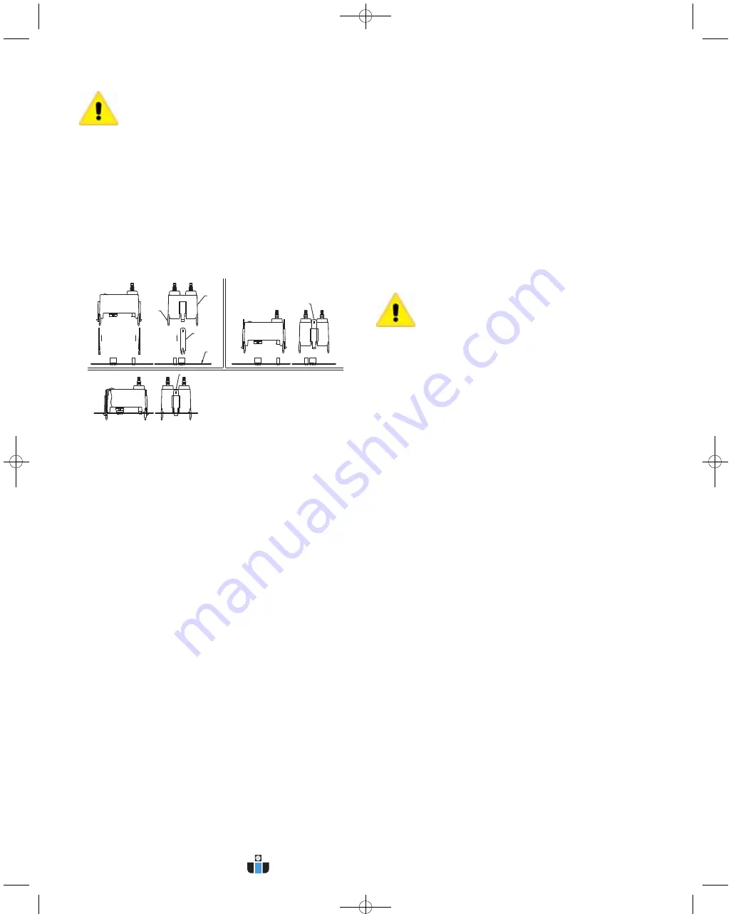
1.3.2 Pressure Module Locking Pins
The DCP100A and DCP200A are supplied with locking pins to secure the
module. In normal operation these are not required since the latching
tabs are sufficient to secure the module even in a high vibration
environment. However if the unit is to be shipped or used where severe
mechanical shock could be encountered the locking pins ensure the
module will not snap out of the board.
To install the locking pins, from underneath the module insert one locking
pin behind each of the two latching tabs. Press these all the way into the
channel. The ends of the tabs will extend through the slots at the top of
these channels. Next insert the module in the board as described above,
making sure it is properly aligned and snaps firmly in place. Press the
exposed locking tabs down until the tab is seated behind the latch in the
board. To remove the module, slide the locking tabs up using a small
screw driver then remove the module as described above. See Figure 3.
1.3.3 Connecting DCP to Master Controller
The pressure module is attached to the Master Controller using integral
connectors on both units. The insertion ports for the pressure module are
located in the upper left quadrant of the DCT1000DC. The pressure
module can be removed by compressing the retaining clips on each end
of the module, then gently pulling the module out of the controller board.
When inserting the module, the following procedure should be adhered to
insure proper installation:
• Examine the bottom of the pressure module and note the orientation of
the connectors.
• Align the module so that these connectors match the connector
receptacles on the controller board.
• Orient the module with the four alignment pins over their respective
mounting holes.
• Gently press the module into the connectors and snap the retaining clips
on either end of the module into their slots.
• Always install and service this device with the power off and a lockout
installed if required. “Hot” plugging the pressure module into an operating
system may damage the system or cause the calibration parameters to
be erased.
When installing or removing the module make sure to orient the module
straight with board. Installing or removing the module at any angle may
break the alignment pins.
Caution:
Do not force the module into the connectors. Forcing
the insertion may damage the connectors. Properly aligned,
the module should snap into place.
1.3.4 DCP Connections
When a pressure module is installed, the 4-20 mA process signal and the
alarm relay contacts are available. The 4-20 mA circuit is isolated from
ground and other signals. The alarm relay contacts are isolated, normally
open contacts. Pressure connections may be made to the stepped hose
barbs with either 1/8˝ (3.18 mm) or 3/16˝ (4.76 mm) I.D. tubing.
1.3.5 DCP Maintenance
The pressure module should require very little maintenance under normal
operational conditions. However, periodic calibration may be desirable to
assure accuracy of the readings. The module may be removed and
returned to the factory for calibration.
1.4 Alarm Mode Switch Connection
The auto alarm reset is controlled by the alarm mode switch connection.
To enable the auto alarm reset the alarm mode input must be connected
to a common connection. A jumper may be used when auto alarm reset
is always active. A switch may be used if there are times that the auto
alarm reset must be disabled. The switch must be an isolated contact and
wired such that no connection is made between either of the wires and
ground. See Figure 2 Wiring Connections.
1.4.1 Alarm Reset Switch Connection
The alarm may be reset either by pressing the Alarm Reset button on the
control panel or by an external switch connected between the alarm-reset
terminal and one of the common terminals. The alarm reset will only
operate if the pressure module is installed and the pressure has returned
to a normal condition. See Figure 2 Wiring Connections.
1.4.2 Connecting the 4-20 mA Loop
The pressure module provides an isolated 4-20 mA output, which may be
used to remotely monitor the differential pressure across the dust bags or
cartridges. The connection is made on the master control module at the
terminal block designated for this signal. The connection is a 2-wire
configuration with the option of using either an external 15 to 35 VDC
power source or using the internal 24 VDC source. See Figure 2 Wiring
Connections.
ALIGNMENT
PINS
PRESSURE
MODULE
LOCKING PINS
INSERTED FROM
UNDERNEATH
MODULE ONLY
CIRCUIT
BOARD
LOCKING PINS INSERTED
ALL THE WAY INTO THE
CHANNEL
INSERT LOCKING PINS UNTIL THEY SNAP FIRMLY IN PLACE
Figure 3
DCP Installation
E-97DC:e-97DC 10/5/10 8:27 AM Page 5
www.calcert.com
1.888.610.7664
0
5
10
15
20
25
30


