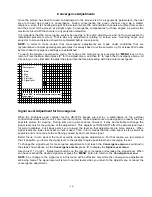
Dwin HD-700 Скачать руководство пользователя страница 14

- 14 -

1.  Size

Press 

“1”

 to select 

“Size”

 adjustment

Adjust the height and width by using the 

/ / /

 arrow buttons to fill the proper aspect ratio for

your screen.

2.  Tilt

Tilt

 adjustments make certain that images are parallel to the edges of the screen, regardless of any

errors that may be induced in the physical installation of the projector. When making 

tilt

 adjustments

you may wish to use a carpenter’s level to make certain that the actual settings are accurate.

At the Tilt adjust screen, use the

  /

 buttons on the remote to adjust the picture until the vertical line

at the center of the screen is straight up and down.  This line will be indicated by hash-marks.  Use
the 

/

 buttons on the remote to adjust the picture until the horizontal line at the center of the

screen is straight across.
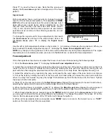
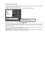
3.  Pin

Pin adjustments are necessary to ensure that the line indicated by hash-marks is straight at the
edges.  After you've corrected for TILT, press "3" and repeat the procedure for PIN.

Now press "SEL" button to close the cursor square and use the left cursor button to move the cursor
square to the left edge of the screen.

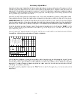
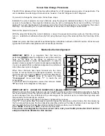
IMPORTANT: Always follow a CENTER to  LEFT  to  TOP  to  RIGHT  to  BOTTOM  pattern  when
adjusting GREEN, RED and BLUE Geometry.  As shown below:


Center

Left

Top

Right

Bottom

The left edge line of the screen is now indicated by hash-marks.  Open the cursor by pressing Select
and make the necessary adjustments for both TILT and PIN to the far left edge line.

Press Select again to close the cursor and move to the top of the screen using the 


arrow key.

Repeat TILT and PIN adjustments.

Repeat TILT and PIN adjustments at the right and bottom edges.
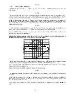
4. Lin

This adjustment permits you to adjust the relationship of the geometry from one side of the picture to
the other.

At the Linearity adjust screen, use the 

/

 buttons on the remote to adjust the picture until left and

right halves of the picture are equal, and 


use

  /

 buttons  on the remote to adjust the picture until

top and bottom halves are equal.

At this point you may press 

“8” 

to proceed with the Red Geometry adjustments, or press “

MENU”

 to

exit.

Содержание HD-700

Страница 1: ...RDATA PROJECTION MONITOR Installation and Operating Instructions Read these instructions completely before operating this unit Contents subject to change without notice or obligation Printed in USA HD...

Страница 2: ...stments __________22 Size Adjustments ________________22 Source Memory Entry __________22 Global Setup Adjustments __________23 Power On Control ________________23 Menu Access ________________23 Menu...

Страница 3: ...his is a safety feature If you are unable to insert the plug fully into the outlet contact your electrician to replace your obsolete outlet Do not defeat the safety purpose of the polarized plug 10 Ro...

Страница 4: ...FCC Rules The limits are designed to provide reasonable protection against harmful interference in a residential installation This equipment generates uses and can radiate radio frequency energy and...

Страница 5: ...lines Video Bandwidth 75 MHz 3 dB Resolution Compatible with HDTV formats and computer graphics up to XGA at native rate Input RGB 0 7V p p 75 ohm positive BNC H V Sync 0 7 4 0 V p p 75 ohM negative B...

Страница 6: ...ain that the projector to screen distance is correct for the size and aspect ratio of the screen Adjust the unit while it is easily accessible BEFORE mounting it to a ceiling or placing it in the fina...

Страница 7: ...nses Plan for connections to the projector of AC power RGBS connections from the signal source and a DB 9 connection if the RS 232C port will be used for external control A separate and properly groun...

Страница 8: ...g on and off power is connected to the unit this indicates that the unit is in the standby mode When the LED is on the unit is powered on NOTE Depending on the configuration of the Auto Power the unit...

Страница 9: ...evel and parallel to the floor You may wish to verify this with a standard carpenter s level In order to make certain adjustments it is necessary to remove the front portion of the unit s top cover Re...

Страница 10: ...e HD 700 ON 2 To turn the HD 700 OFF press the POWER button 3 Press MENU button to view the Main Control Menu at any time Pressing the MENU button while a sub menu is displayed on the screen will retu...

Страница 11: ...1 5 kHz 60 00 Hz 8 Adjust 9 Set Up HD 700 50 FF If the menu is not in clear focus adjust the optical focus on the green lens Loosen the back wing nut and rotate the lens barrel by holding the lens wit...

Страница 12: ...1 to display the Green Focus adjustment screen 2 Adjust the overall optical focus by loosening the wing nut at the rear of the green center lens so that it is loose but do not remove it Rotate the le...

Страница 13: ...en Size Change Procedures are completed before attempting to adjust the geometry Once the projector has been focused select the Geometry Adjustments by first pressing MENU on the remote and then to di...

Страница 14: ...the procedure for PIN Now press SEL button to close the cursor square and use the left cursor button to move the cursor square to the left edge of the screen IMPORTANT Always follow a CENTER to LEFT...

Страница 15: ...annel so that it matches the green channel Use the buttons until the red line that runs directly though the vertical center of the screen covers the underlying green line Then use the buttons until th...

Страница 16: ...for the HD 700 s images are set by a combination of the external controller decoder and the unit s own internal controls those adjustments are designed to present the best possible picture for viewin...

Страница 17: ...mental note of the areas where there is the greatest amount of divergence of red from green as these are areas where you will want to pay special attention to convergence To proceed to the next step f...

Страница 18: ...emote as the letters change on the display Use the left right arrow buttons to move the typing position to the next letter When you have typed YES press the ENTER button and the convergence memory wil...

Страница 19: ...ern Two gray scale adjustments are available for each of the three color channels gain and level Gain impacts the lighter or right side of the test pattern while level impacts the black or left side o...

Страница 20: ...p there should be no need to make a further adjustment at this time However it is good practice to check the setting at this point in the installation This will also familiarize you with the operation...

Страница 21: ...of it off To adjust blanking press Menu to call up the Main Menu and press 5 to access the main Blanking screen At the Blanking screen you have the ability to individually select the top bottom left...

Страница 22: ...HD 700 has a number of global settings that address certain aspects of the projector s operation They should be adjusted to the preferences of the end user before the set is delivered 1 Power On Cont...

Страница 23: ...ENU and then 9 to reach the Set Up menu Press 2 to access the Menu Control System Noting that Protected will be highlighted press to indicate that you wish to enable the menu control system Once you p...

Страница 24: ...use the button to move to the next spot and the and arrow buttons to select the character When the complete input name or designator is on screen press ENTER to save the source name and settings to me...

Страница 25: ...press Enter memories for 1 85 4 3 and 2 35 are now automatically entered Preparation for installation Once the unit has been configured for operation and all settings established it may be taken to th...

Страница 26: ...stem should be protected Protecting the menu system will restrict the user s access to the setup menus so that your calibrations will not be disturbed Some users however will insist on the ability to...

Страница 27: ...ystem to make the adjustment In order to preserve memory space for normal convergence adjustments it is very important that a echanical alignment be performed when the screen size is changed When thre...

Страница 28: ...Data Parity none 3 RX Receive Data Stop bits 1 5 GND Signal Ground Num of bits 8 bits Flow control none Each command is enclosed in the character envelope The following table lists the commands avail...

Страница 29: ...in design appearance or construction This warranty covers only the actual defects within the PRODUCT itself and DOES NOT cover the costs of installation or removal from a fixed installation normal se...

Отзывы: