background image

trk100/trk100d/trk200 Installation Manual 

12 

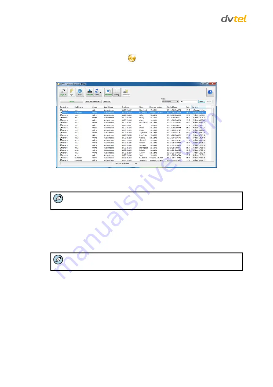
To change the unit’s IP address 

1. 

Insert the CD included in the package in your computer’s disk drive. 

2. 

Run the 

dna.exe

 file by clicking the 

 icon. The DNA application opens and the device is 

displayed in the window. 

3. 

Select the unit by right-clicking on it. 


Figure 8: DNA Discovery Window 

4. 

In the Unit network configuration area, enter the IP address, Subnet mask, and Gateway IP 
address. 


Note:


It is possible to set the IP address without changing the subnet. 

5. 

If you use a DHCP server, select the 

DHCP

 checkbox. 

6. 

You may change the IP address for a single unit or multiple units. 


To change the IP address for a single unit, select 

Update single

. The IP address is changed. 


To change the IP address for a number of units, enter the IP address of the first unit in the 
series. Then select 

Update batch

. The IP addresses are changed. 


Note:


The unit and the PC must be physically connected on the same subnet. 

3.2.4


Connecting the Video Source (Camera) to the Unit 

The unit accepts composite video input (1Vp-p) from stationary and/or PTZ analog cameras (standard, 
thermal, IR, etc.). Video connections should use a 75Ω cable and should not be longer than 30 meters (98 
feet). 

To connect a video source to the unit 

1. 

Securely connect the BNC video cable connector to the analog video output of the camera or 
video source. 

2. 

Connect the BNC connector at the other end of the cable to the Video In connector of the 
required channel on the back panel of the unit. See Figure 5: trk100/trk100d Back Panel  
(page 4) and Figure 7: trk200 Back Panel (page 6)

Содержание ioimage trk100

Страница 1: ...stallation Manual Rev E March 2014 The contents of this manual may not be reproduced or reprinted in whole or in part without the express written permission of DVTEL INC DVTEL INC 65 Challenger Road R...

Страница 2: ......

Страница 3: ...he Unit 12 3 2 5 Connecting a Microphone to the Unit 13 3 2 6 Connecting a Loudspeaker to the Unit 14 3 2 7 Connecting PTZ Camera Control Lines to the Unit 14 3 2 8 Connecting the Analog Video Output...

Страница 4: ...ront Panel 3 Figure 5 trk100 trk100d Back Panel 4 Figure 6 trk200 Front Panel 5 Figure 7 trk200 Back Panel 6 Figure 8 DNA Discovery Window 12 Figure 9 Microphone Connection to the Unit 13 Figure 10 Lo...

Страница 5: ...allation and Setup Guide 1 2 July 2004 Elisabeth Levy Second release 1 3 October 2004 Elisabeth Levy Third release Ver A2 August 2009 Leigh Includes trk100d and trk200 Rev D April 2013 Alan Singer Add...

Страница 6: ......

Страница 7: ...ons This document contains proprietary information belonging to DVTEL Inc This information is supplied solely for the purpose of assisting explicitly the licensee of the DVTEL units No part of this do...

Страница 8: ...nual A Warning is a precautionary message that indicates a procedure or condition where there are potential hazards of personal injury or death A Caution is a precautionary message that indicates a pr...

Страница 9: ...otherwise attempt to bypass the ground pin of the power cord Do not operate the unit in the absence of a suitably installed ground conductor 5 If you use an extension cord with this system make sure...

Страница 10: ...ripping wire fraying overheating etc Ensure that nothing rests on the unit s cables or power cords Ample Air Circulation Leave enough space around the unit to allow free air circulation Cabling Consid...

Страница 11: ...red video signal generates alarms and notifies operators of the presence of people vehicles or objects It can stop and detect events in multiple preset zones Users can define the events and location i...

Страница 12: ...nal block spring clamp connectors for relay outputs and alarm inputs 1 Documentation and utilities CD Note An AC adaptor matching the unit s electrical specifications part number DVT PWR 40W can be pu...

Страница 13: ...nal after analysis and includes detection overlays and additional On Screen Display OSD information Typically connected to analog video equipment such as analog video displays or analog video recordin...

Страница 14: ...ive alarm signals from an external device for example a fire sensor PIR passive infrared sensor fence sensor etc with a dry contact output to the terminal block Four independent alarm inputs are avail...

Страница 15: ...etection One BNC connector is provided for each video channel VIDEO OUT BNC Output interfaces channels 1 and 2 that provide the analog video signal after analysis and include detection overlays and ad...

Страница 16: ...it page 10 2 2 2 2 trk200 Back Panel The following image shows the back panel of the trk200 unit Figure 7 trk200 Back Panel The back panel of the unit includes the following connections Item Descripti...

Страница 17: ...put signal opto isolated used to provide an indication signal for controlling a single external device such as an electrical door lock Two independent relay outputs are available for use by any channe...

Страница 18: ......

Страница 19: ...ions for example sunlight rain dust etc Caution To avoid damage from overheating or unit failure ensure that there is sufficient temperature regulation to support the unit s cooling heating requiremen...

Страница 20: ...ng the required specifications can be purchased as an accessory from DVTEL Caution Before connecting to the power review the Electrical Safety Notice and Warnings page vii To power to the unit from a...

Страница 21: ...at the unit can be found on the network as described below Note Refer to the HTML Edition Units User s Guide for configuring required firewall settings To connect a unit to the network 1 Connect a PC...

Страница 22: ...ingle The IP address is changed To change the IP address for a number of units enter the IP address of the first unit in the series Then select Update batch The IP addresses are changed Note The unit...

Страница 23: ...u also can connect a separate audio input device for each camera channel Figure 9 Microphone Connection to the Unit The audio input to the unit is connected to a LINE IN interface and must meet the fo...

Страница 24: ...e 6 trk200 Front Panel page 5 2 Connect the Audio Output RCA connector at the other end of the audio splitter cable to the input of the audio device amplifier 3 Connect loudspeaker to the amplifier 3...

Страница 25: ...e unit s web interface Connect the VIDEO OUT connector for each channel to separate analog output devices The analog video output can be monitored using an analog monitor or recorded on a digital vide...

Страница 26: ...n external device regardless of whether the device is operated in a NORMALLY OPEN or NORMALLY CLOSED configuration NO Terminal for connecting one of a pair of wires that leads to an external device on...

Страница 27: ...panel of the camera 2 Press in and release The unit resets to the previous settings 3 3 2 Reset by Removing the Power Supply The unit can be reset by turning off the power and then turning it on agai...

Страница 28: ...0 Installation Manual 18 Appendix The appendix contains the following sections Technical Specifications page 19 Connecting Leads to a Spring Clamp Terminal Block page 21 Solo Setup Window page 22 Trou...

Страница 29: ...o Output IP Video Streaming MPEG 4 SP and MJPEG Maximum Resolution per Channel CIF Channel 1 4CIF Channel 2 CIF CIF Frame Rate MPEG 4 SP Up to 25 30 fps PAL NTSC for all resolutions Bit Rate CBR 128Kb...

Страница 30: ...36 x 164 mm W x H x D Dimensions inches 7 7 16 x 1 13 32 x 6 7 16 W x H x D Mounting Shelf mount Environmental Specifications Operating Temperature 0 to 50 C 32 to 122 F Operating Humidity 5 to 95 non...

Страница 31: ...connect a wire to the spring clamp terminal block 1 Strip the insulation form the end of each wire that is to be connected to the terminal block Approximately 1 cm 2 54 of wire should be exposed 2 Wi...

Страница 32: ...ing control icons are available on the Solo Setup keypad Icon Function Notes Start Recording Starts recording and browses to destination folder where the clip will be saved Stop Recording Stops record...

Страница 33: ...ons in the HTML Edition Units User s Guide 8 Click Browse to load the clip from the folder where it is saved 9 Use the Play Pause Fast Forward and Rewind buttons on the Solo Setup keypad to explore th...

Страница 34: ...on See Connecting the Unit to the Network The IP address responds to a ping on the network from the workstation but does not show in the DNA application Disconnect the unit s Ethernet 10 100 port or t...

Страница 35: ...tings Refer to the HTML Edition Units User s Guide for details Refresh your browser screen F5 Check that the bandwidth and bit rate settings of the network are set properly Check that other processes...

Страница 36: ...t a proper rule for activating a relay output has been defined in the unit or activate it manually Refer to the HTML Edition Units User s Guide for details Check the relay output wires are connected s...

Страница 37: ...44 0 1494 446928 INDIA AND SAARC DVTEL Gesco Corporate Centre The Great Eastern Centre 70 Nehru Place New Delhi 110019 India Cel 91 129 431 5031 Fax 91 11 26209302 CALA DVTEL Mexico S A P I de C V Av...

Отзывы: