


Setup
Operating Instructions 878-M PREMIUM - 06.0 - 11/2021
154
8.7 Controller
8.7.1
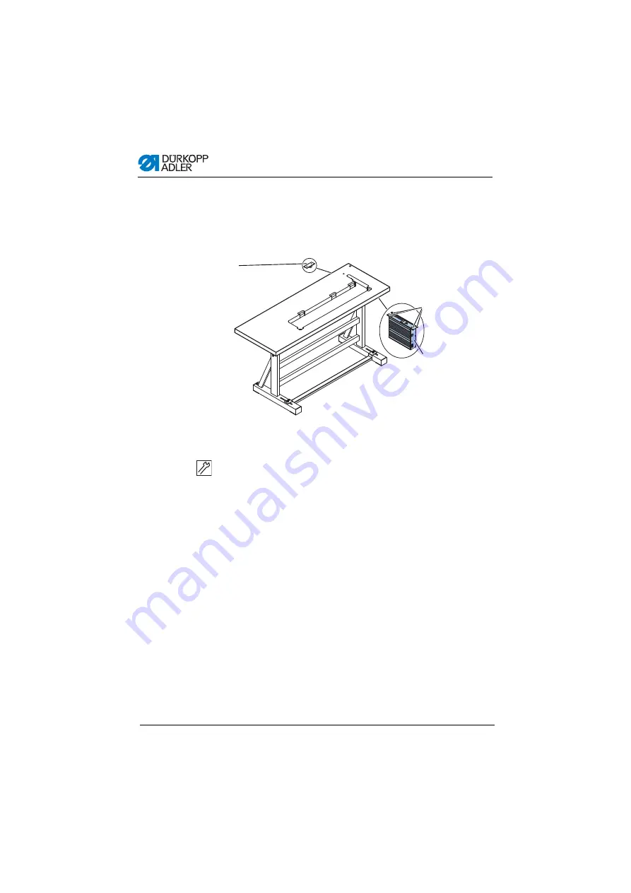
Fitting the control unit
Fig. 77: Fitting the control unit
1. Screw the control unit (2) onto the 4 screw holders (3) under the
table top.
2. Clamp the power cable of the control unit (2) into the strain
relief mechanism (1).
3. Screw the strain relief mechanism (1) under the table top.
3
2
1
(1) - Strain relief
(2) - Control unit
(3) - Screw holder
Содержание 878-160722-M
Страница 1: ...878 M PREMIUM Operating Instructions...
Страница 6: ...Obsah 4 Operating Instructions 878 M PREMIUM 06 0 11 2021...
Страница 14: ...Safety Operating Instructions 878 M PREMIUM 06 0 11 2021 12...
Страница 146: ...144 Operating Instructions 878 M PREMIUM 06 0 11 2021...
Страница 174: ...Disposal 172 Operating Instructions 878 M PREMIUM 06 0 11 2021...
Страница 176: ...Appendix 174 Operating Instructions 878 M PREMIUM 06 0 11 2021 Dimensions for manufacturing part 2...
Страница 177: ...Appendix Operating Instructions 878 M PREMIUM 06 0 11 2021 175 10 2Component layout on underside of table top...
Страница 178: ...Appendix 176 Operating Instructions 878 M PREMIUM 06 0 11 2021 10 3Interconnection diagram...
Страница 179: ......


