


22
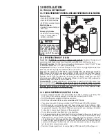
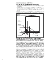
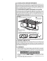
3.13.1 CONFIGURING UNIT FOR 208 VOLT POWER
The control transformer in 208/240V air-handlers must be configured in the field to oper-
ate on a 208 volt electrical supply to assure adequate control voltage (24+ volts) with the
reduced supply voltage. The units are shipped from the factory for 220-240 volt appli-
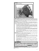
cations. For 208 volt applications, disconnect electrical power to the unit and remove
the blower access panel and then the control box cover located on the blower housing.
Then remove the insulated cap from the 208 volt transformer terminal and move the
BLACK wires that are connected to the 240 volt transformer terminal to the 208 volt
transformer terminal. Plug the insulated cap onto the transformer 240V terminal.
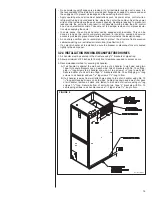
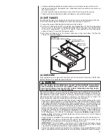
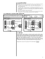
3.13.2 GROUNDING
• This product must be sufficiently grounded in accordance with National Electrical
Code (C.E.C. in Canada) and any applicable local ordinance.
• Grounding may be accomplished by grounding metal conduit when installed in accor-
dance with electrical codes to the unit cabinet.
• Grounding may also be accomplished by attaching ground wire(s) to ground lug(s)
provided in the unit wiring compartment.
• Ground lug(s) are located close to wire entrance on left side of unit (upflow). Lug(s)
may be moved to marked locations near wire entrance on right side of unit (upflow), if
alternate location is more convenient.
• Use of multiple supply circuits require grounding of each circuit to lug(s) provided in unit.
3.13.3 POWER WIRING
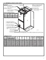
It is important that proper electrical power is available for connection to the unit model being
installed. See the unit nameplate, wiring diagram and electrical data in the installation instructions.
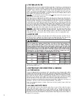
• If required, install a branch circuit disconnect of adequate size, located within sight of, and readi-
ly accessible to the unit.
• IMPORTANT:
Units with electric heater kits installed may be equipped with one, two, or three
30/60 amp circuit breakers. These breaker(s) protect the internal wiring in the event of a short
circuit and serve as a disconnect. Circuit breakers installed within the unit do not provide
over-current protection of the supply wiring and therefore may be sized larger than the branch
circuit protection.
• Supply circuit power wiring must be 75°C minimum copper conductors only. See Electrical Data
in Sections 3.13.5 and 3.13.6 for ampacity, wire size and circuit protector requirement. Supply
circuit protective devices may be either fuses or “HACR” type circuit breakers.
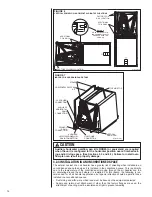
• Field power wiring may be connected to either the right, left side or top. Three
7
/
8
”, 1
3
/
32
”, 1
31
/
32
” dia.
concentric knockouts are provided for connection of power wiring to unit.
• Field power wiring is to be connected to the power terminal block in unit control compartment.
• For units equipped with an electric heater kit, field power wiring is to be connected to the heater
kit breaker, terminal block, or pullout disconnect terminals and the power wiring pigtail from the
heater kit is to be connected to the unit power terminal block in the unit control compartment.
Refer to installation instructions provided with the heater kit for additional details.
WARNING
The unit must be permanently grounded. Failure to do so can result in electri-
cal shock causing personal injury or death.
!
S
U
P
P
L
Y
W
I
R
E
L
E
N
G
T
H
F
E
E
T
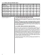
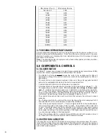
SUPPLY CIRCUIT AMPACITY
NOTE: WIRE BASED ON COPPER CONDUCTORS 75°C MINIMUM RATING.
FOR MORE THAN 3 CONDUCTORS IN A RACEWAY OR CABLE, SEE
N.E.C. FOR DERATING THE AMPACITY OF EACH CONDUCTOR.
12
12
14
14
15
10
10
12
12
20
8
10
10
10
25
8
10
10
10
30
8
8
8
8
35
6
8
8
8
40
6
6
8
8
45
6
6
6
6
50
4
6
6
6
60
4
4
4
4
70
3
4
4
4
80
3
3
3
3
90
2
3
3
3
100
2
2
2
2
110
1
1
1
1
125
0
0
0
0
150
00
00
00
00
175
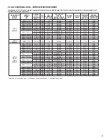
3.13.4 COPPER WIRE SIZE - AWG. (3% VOLTAGE DROP)
200 [61]
150 [46]
100 [30]
50 [15]
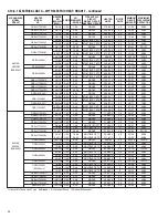
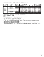
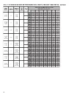
3.13.5.1 ELECTRICAL DATA – BLOWER MOTOR ONLY – WITHOUT ELECTRIC HEAT: DRAH1T
MODEL
DRAH1T
VOLTAGE
PHASE*
HERTZ
HP
RPM
SPEEDS
MOTOR
AMPS
MINIMUM
CIRCUIT
AMPACITY
MAXIMUM
OVERCURRENT
PROTECTION
2417AS
208/240
1 & 3
60
1/3
300-1100
4
1.6
2
15
3617AS/3621AM/3621AH
1/2
300-1100
4
2.8
4
15
4821AS/4821AM
3/4
300-1100
4
4.0
5
15
6021AS/6024AS/4824AS
3/4
300-1100
4
4.6
6
15