


14
CAUTION
Auxiliary horizontal overflow pan kits RXBM- (or equivalent) are required
when the unit is configured for the horizontal position over a finished ceil
-
ing and/or living space. (See Sections 3.3 and 6.3.) Failure to install over
-
flow plan can result in property damage.
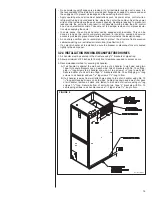
3.2.3 INSTALLATION IN AN UNCONDITIONED SPACE
The exterior cabinet of an air handler has a greater risk of sweating when installed in an
unconditioned space than when it is installed in the conditioned space. This is primarily
due to the temperature of the conditioned air moving through the air handler and the
air circulating around the unit where it is installed. For this reason, the following is rec-
ommended for all air handler applications, but special attention should be paid to those
installed in unconditioned spaces:
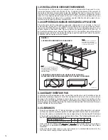
• Duct sizing and airflow are critical and must be based on the equipment selected.
• Supply and return duct attachment: If other than the factory flanges are used, the
attachment of ducting must be insulated and tight to prevent sweating.
!
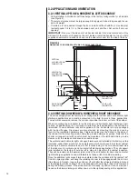
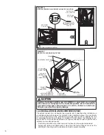
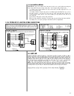
FIGURE 6
VERTICAL DOWNFLOW & HORIZONTAL RIGHT APPLICATIONS
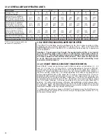
FIGURE 7
INDOOR COIL AND DRAIN PAN DETAILS
ST-A1213-01
HORIZONTAL DRIP PAN
KIT
TOP AIR STOP
STRAPS
VAPOR LINE
CONNECTION
PRIMARY
DRAIN
CONNECTION
LIQUID LINE
CONNECTION
VERTICAL
DRAIN PAN
AUXILIARY
HORIZONTAL
DRAIN
CONNECTION
AUXILIARY
UPFLOW/DOWNFLOW
DRAIN CONNECTION
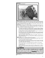
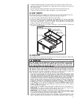
DETAIL A
ENSURE THE RETAIN-
ING CHANNEL IS FULLY
ENGAGED WITH THE
COIL RAIL.
ADDITIONAL
COIL RAILS
FACTORY COIL RAIL LOCATION
ST-A1213-02
FACTORY COIL
RAIL LOCATION
ADDITIONAL
COIL RAILS