


21
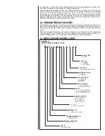
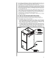
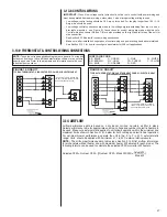
FIGURE 13
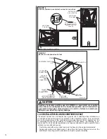
CONDENSATE DRAIN TRAP
ST-A1244-01-01
• Do not reduce drain line size less than connection size provided on condensate drain
pan
.
• All drain lines must be pitched downward away from the unit a minimum of 1/8” per
foot of line to ensure proper drainage.
• Do not connect condensate drain line to a closed or open sewer pipe. Run conden-
sate to an open drain or outdoors.
• The drain line should be insulated where necessary to prevent sweating and damage
due to condensate forming on the outside surface of the line.
• Make provisions for disconnecting and cleaning of the primary drain line should it
become necessary. Install a 3 in. trap in the primary drain line as close to the unit as
possible. Make sure that the top of the trap is below connection to the drain pan to
allow complete drainage of pan (See Figure 13).
• The auxiliary drain line should be run to a place where it will be noticeable if it
becomes operational. The building occupant should be warned that a problem exists
if water should begin running from the auxiliary drain line. An auxiliary drain shut-off
switch can be installed in lieu of an auxiliary drain line. The shut-off switch should be
wired into the control circuit so the outdoor unit shuts down should the switch detect
water.
• Plug the unused drain connection with the plugs provided in the parts bag, using a
thin layer of teflon paste, silicone or teflon tape to form a water tight seal.
• Test the condensate drain pan and drain line after installation is complete. Pour water
into drain pan, enough to fill drain trap and line. Check to make sure drain pan is
draining completely, no leaks are found in drain line fittings, and water is draining from
the open end of the primary drain line
.
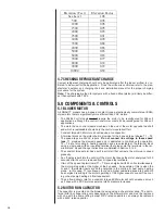
3.12 THERMOSTAT
See instructions for the condensing unit or heat pump for recommended room thermostats.
• On units with one electric heat sequencer (TD
1
) (see wiring diagram for electric heat-
er), heat anticipator setting should be .16.
• On units with two electric heat sequencers (TD
1
& TD
2
) (see wiring diagram for elec-
tric heater), heat anticipator setting should be .32 if both are connected to same stage
on thermostat. Setting should be .16 if (TD
1
& TD
2
) are connected to separate stages.
NOTE:
Some thermostats contain a fixed, non-adjustable heat anticipator.
Adjustment is not permitted.
• The thermostat should be mounted 4 to 5 feet above the floor on an inside wall of the
living room or a hallway that has good air circulation from the other rooms being con-
trolled by the thermostat. It is essential that there be free air circulation at the location
of the same average temperature as other rooms being controlled. Movement of air
should not be obstructed by furniture, doors, draperies, etc. The thermostat should
not be mounted where it will be affected by drafts, hot or cold water pipes or air ducts
in walls, radiant heat from fireplace, lamps, the sun, T.V. or an outside wall. See
instruction sheet packaged with thermostat for mounting and installation instructions.
3.13 ELECTRICAL WIRING
Field wiring must comply with the National Electric Code (C.E.C. in Canada) and any
applicable local ordinance.