DURASTAR DRAH1T Скачать руководство пользователя страница 19

19

3.9.3 BRAZING

Air inside the tubing and coil should be displaced with dry nitrogen prior to the brazing 

process to prevent the formation of harmful copper oxide inside the tubing.  It is very 

important not to pressurize the system with nitrogen while brazing or pin-hole leaks will 

form in the braze joint. This is accomplished by removing the gauge port valve core on 

one of the outdoor unit service valves to allow the pressure to be relieved as the heat-

ed nitrogen expands.  Fill the system with dry nitrogen through the other service valve 

gauge port and then turn the nitrogen flow off just before brazing is begun.

Protect  the  TXV,  copper  to  aluminum  suction  header  joint,  and  outdoor  unit  service 

valves from overheating using a wet rag or heat sink compound.  Leave the wet rag or 

heat sink material in place until the joint and surrounding tubing cools down to a safe 

temperature.  Double tip torches can help minimize brazing time and heat conduction 

to the heat sensitive components if the flame is turned down and held on the joint just 

long enough to make the braze joint.  With both single and double tip torches, turning 

the flame up too much and keeping the flame on the joint too long will damage the heat 

sensitive components even when a wet rag or heat sink compound is used.

Use a sheet metal shield to protect the cabinet’s paint from the torch flames during the braz-

ing process.  The vapor line insulation should be pushed back on the line about 12 inches 

from the joint and retained to prevent it from igniting or melting during the brazing process.

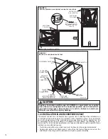
After the refrigerant brazed connections are made at the air-handler and the tubing has 

cooled down sufficiently, replace the coil section access panel if it has been removed 

and seal the air gap around the connection stubs with the foam rubber gasket included 

in the air-handler parts bag.  Peel the self-adhesive backing off of the foam gasket and 

position it around the stubs with the adhesive side toward the cabinet, then press it firm-

ly against the cabinet.  The gasket is split to allow it to go over the stubs after the refrig-

erant tubes are brazed to the stubs.  (See Figure 12 in Section 3.10)

After the foam gasket has been installed, the vapor line insulation should be pulled back 

in place so it contacts the air-handler cabinet to prevent condensate from forming on the 

cold tube and dripping off.  A loosely fitting zip-tie placed around the insulation ½” from 

the end can be used to hold it in place so it doesn’t move away from the cabinet. For 

air-handlers with TXV’s, a section of the insulation will need to be cut out to make room 

for the externally mounted TXV bulb. 

(See Section 3.10)

  Once the bulb is mounted, 

insulate the bulb with the foam insulation included in the air-handler parts bag, making 

sure none of the vapor line is uninsulated.

3.9.4 LEAK TESTING

After all braze joints are completed, replace the valve core removed when purging with 

nitrogen and then leak test the system by pressurizing to 150 psig with dry nitrogen and 

allow the system to sit for at least 15 minutes (longer if possible) to assure the pressure 

does not drop.

3.9.5 EVACUATION

If no leaks are detected, evacuate the system down to 500 microns or below before 

charging the system or opening the service valves on the outdoor unit which will release 

the charge stored in the outdoor unit into the line set and air-handler coil.  Failure to 

reach 500 microns of vacuum is a sign of a leak or excessive moisture inside the system.

3.9.6 REFRIGERANT CHARGING

Once the evacuation process is completed, break the vacuum with the refrigerant from a 

refrigerant cylinder or with refrigerant stored in the outdoor unit by opening the outdoor 

unit  service  valves.    The  charging  process  cannot  be  completed  until  the  remaining 

steps in the installation process are completed and the indoor air-flow is adjusted to the 

proper level.  See Section 4.7 for further details.

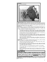
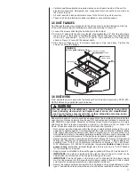
3.10 TXV SENSING BULB ATTACHMENT

IMPORTANT: 

DO NOT perform any brazing with the TXV bulb attached to the vapor 

line. After brazing operations have been completed and the tubing has cooled to the 

touch, clamp the TXV bulb securely on the vapor line at the 10 to 2 o’clock position (see 

Figures 11 and 12) with the strap provided in the parts bag. Insulate the TXV sensing 

bulb and suction line with the provided pressure sensitive insulation (size 4” × 7”) and 

secure with provided wire ties.

IMPORTANT: TXV sensing bulb should be located on a horizontal section of suc-

tion line, just outside of coil box. The copper sensing bulb must never be placed 

on any aluminum tube as this will result in galvanic corrosion and eventual failure 

of the aluminum tube.

Содержание DRAH1T

Страница 1: ...nstallation adjustment and operation of this unit Read these instructions thoroughly before attempting installation or operation Failure to follow these instructions may result in improper installatio...

Страница 2: ...factured Homes 15 3 2 5 Installation in Corrosive Environments 16 3 2 6 Supporting Air Handler in Horizontal Applications 16 3 3 Auxiliary Overflow Pan 16 3 4 Clearances 16 3 5 Duct Flanges 17 3 6 Duc...

Страница 3: ...5 4 6 Checking Indoor Air Flow 35 4 6 1 Estimating CFM Using External Static Pressure 35 4 6 2 Estimating CFM Using Electric HEat Temperature Rise 35 4 7 Checking Refrigerant Charge 36 5 0 COMPONENTS...

Страница 4: ...aled to prevent depres surization of the space and possible migration of combustion byproducts including carbon monoxide into the living space WARNING SEE SECTION 3 6 DUCTWORK Do not under any circums...

Страница 5: ...d to the supply air opening from the downflow unit Exposing combus tible non metal material to the supply opening of a downflow unit can cause a fire resulting in property damage personal injury or de...

Страница 6: ...e in place Correct air flow setting for application Removing the coil and storing it in a clean safe place is highly recom mended until construction is completed and the outdoor unit is installed Clea...

Страница 7: ...IVED Immediately upon receipt all cartons and contents should be inspected for transit dam age Units with damaged cartons should be opened immediately If damage is found it should be noted on the deli...

Страница 8: ...y secure the third lead The air handlers are shipped from the factory with the proper indoor coil installed and cannot be ordered without a coil These air handlers do not have an internal filter rack...

Страница 9: ...ID LINE CONNECTION COPPER SWEAT VAPOR LINE CONNECTION COPPER SWEAT 2111 16 105 16 SUPPLY AIR W A H 191 2 RETURN AIR OPENING SEE DUCT FLANGES SECTION 3 5 FOR INSTRUCTIONS DIMENSIONAL DATA MODEL SIZE RE...

Страница 10: ...NT This product has been designed and manufactured to meet certified AHRI capacity and efficiency ratings with the appropriate outdoor units However prop er refrigerant charge proper airflow and refri...

Страница 11: ...performed safely with nitrogen or a mixture of R 410A and nitrogen 3 1 3 QUICK REFERENCE GUIDE FOR R 410A R 410A refrigerant operates at approximately 60 higher pressure 1 6 times than R 22 Ensure th...

Страница 12: ...n the sides of the cabinet for the mounting screws using the provided dimples as guides Note that the shorter coil support rail with no notch must be mounted on the left hand side to provide clearance...

Страница 13: ...nsulation is caught in lug Tighten lug as tight as possible while holding circuit breaker Check wires and make sure each wire is secure and none are loose Repeat for left wire bundle in left top circu...

Страница 14: ...rec ommended for all air handler applications but special attention should be paid to those installed in unconditioned spaces Duct sizing and airflow are critical and must be based on the equipment se...

Страница 15: ...ing or a restricted coil drain line See Section 3 3 If an electric heater kit is installed be sure the breaker or disconnect cover is sealed tightly to the door panel 3 2 4 INSTALLATION IN MOBILE MANU...

Страница 16: ...ent containing evaporator coils that are located in any area of a structure where damage to the building or building contents may occur as a result of an overflow of the coil drain pan or a stoppage i...

Страница 17: ...that the system airflow be adequate Make sure supply and return ductwork grills filters accessories etc are accounted for in total resistance Refer to the airflow performance tables in this manual to...

Страница 18: ...nded orifice size for various outdoor units Piston size installed at factory Correct piston for other tonnages will be included with the matching outdoor unit 3 9 REFRIGERANT LINE CONNECTIONS CHARGING...

Страница 19: ...lation should be pulled back in place so it contacts the air handler cabinet to prevent condensate from forming on the cold tube and dripping off A loosely fitting zip tie placed around the insulation...

Страница 20: ...t block service access to front of the unit Minimum clearance of 24 inches is required for filter coil or blower removal and service access Although the condensate drain pan is designed is designed to...

Страница 21: ...d drain line after installation is complete Pour water into drain pan enough to fill drain trap and line Check to make sure drain pan is draining completely no leaks are found in drain line fittings a...

Страница 22: ...the event of a short circuit and serve as a disconnect Circuit breakers installed within the unit do not provide over current protection of the supply wiring and therefore may be sized larger than th...

Страница 23: ...0 35 RXBH 1724A13C 9 4 12 5 3 60 3 4 17 SINGLE 26 1 30 1 1 6 35 40 35 40 3617AS 208 240V RXBH 17 03J 2 25 3 0 1 60 1 3 0 SINGLE 10 8 12 5 2 8 17 20 20 20 3617AS 3621AM 3621AH 208 240V RXBH 1724 03J 2...

Страница 24: ...0 0 32 37 35 40 RXBH 1724 05J 3 6 4 8 1 60 1 4 8 SINGLE 17 3 20 0 4 6 28 31 30 35 RXBH 1724 07J 5 4 7 2 1 60 2 3 6 SINGLE 26 0 30 0 4 6 39 44 40 45 RXBH 1724 10J 7 2 9 6 1 60 2 4 8 SINGLE 34 6 40 0 4...

Страница 25: ...or load is included in single circuit or circuit 1 of multiple circuits Heater loads are balanced on 3 phase models with 3 or 6 heating elements only Electric heater kits are not permitted for use wit...

Страница 26: ...wiring where the breakers apply has been UL approved for short circuit protection Ampacity not breaker size determines supply circuit wire size The ampacity listed on the unit rating plate and the Ma...

Страница 27: ...performance operate the unit in the 3 to 7 in W C external static range Units should be applied with a minimum of 1 in W C external static pressure NOTE The air flow performance data tables see Sectio...

Страница 28: ...Speed tap T1 is always dedicated to continuous fan operation and delivers approximately 50 of the speed tap T4 air flow Speed taps T2 T4 are for applications with an external static pressure up to 0...

Страница 29: ...96 1017 480 977 461 935 441 671 725 764 809 852 153 168 174 180 188 1084 512 1040 491 1001 472 896 936 971 249 257 261 1068 504 1025 484 992 468 952 449 910 429 711 765 804 849 892 164 179 185 191 199...

Страница 30: ...5 3 2 CFM RPM Watts CFM RPM Watts CFM RPM Watts CFM RPM Watts CFM RPM Watts 3621AH No Heat 5 10x10 1 2 Hp 373 2 Speed dual voltage 2 3621AH 18 kW Heat 5 10x10 1 2 Hp 373 2 Speed dual voltage 2 5 10x1...

Страница 31: ...1x11 3 4 559 5 Speed 11x11 3 4 559 5 Speed 11x11 3 4 559 5 Speed 4 5 2 3 2 3 6024AS No Heater 6024AS with 30kW Heater 6024AS No heater 6024AS with 30kw heater CFM RPM Watts CFM RPM Watts 1625 767 1591...

Страница 32: ...4 1069 374 379 386 396 408 423 440 1465 1423 1381 1338 1296 1254 1212 779 816 854 891 929 967 1004 257 270 281 287 290 289 285 CFM RPM Watts 5 1803 1760 1217 1683 1648 1612 1576 886 919 952 988 1019 1...

Страница 33: ...and Y inputs from the thermostat are de energized A time delay programmed into the DRAH1T motor keeps the blower motor energized for an additional 30 seconds to extract the residual cooling from the c...

Страница 34: ...o provide a 3rd stage of heat as needed When the thermostat call is satisfied The G and Y terminals inputs from the thermostat are de energized A time delay programmed into the DRAH1T motor keeps the...

Страница 35: ...ss the filter is accounted for The static pressure inside the supply plenum should be measured at a point about half way between the air handler and the first elbow or the end of the plenum Total exte...

Страница 36: ...eration T2 T5 are for cooling heating operation and are selectable at the terminal block using a single wire with an insulated terminal that plugs onto the terminals in the ter minal block Speed chang...

Страница 37: ...s through the blower access door The blower slides into place on a track and is secured by 4 sheet metal screws 5 5 TRANSFORMER A 40VA transformer is located inside the control box attached to the blo...

Страница 38: ...e are no C Voltage air handlers available C voltage heater kits are for 3 phase applications and allow for smaller wire fuse breaker size compared to single phase J Voltage heater kits The heater kit...

Страница 39: ...he system filter every ninety days or as often as found to be necessary and if obstructed clean or replace at once A qualified installer service agency or HVAC professional should instruct the homeown...

Страница 40: ...mild solvent such as hot water and detergent Be careful not to disturb the balance weights clips on the blower wheel blades Do not drop or bend wheel as balance will be affected 7 4 MOTOR LUBRICATION...

Страница 41: ...een the inlet orifice and outside of blower wheel Tighten setscrew on motor shaft Turn wheel by hand to make sure it runs true without hitting blower sides Reassemble motor wiring to capacitor and mot...

Страница 42: ...V WULSSHG FKHFN IRU ORZ DLU IORZ 2YHU WHPSHUDWXUH OLPLW KDV IDLOHG UHSODFH 6HTXHQFHU RU FRQWDFWRU KDV IDLOHG UHSODFH 2QH RU PRUH KHDWLQJ HOHPHQWV KDYH EXUQHG RXW UHSODFH RLO LV IUR HQ XS 6 VWHP ORZ RQ...

Страница 43: ...43 9 0 WIRING DIAGRAMS 9 1 WIRING DIAGRAM DRAH1T 208 240V 3 0 3 0 2 0 0 0 1 0 2 0 0 0 1 0...

Страница 44: ...44 CM 0720...

Отзывы: