background image

4.2

Changing the Stitch Length

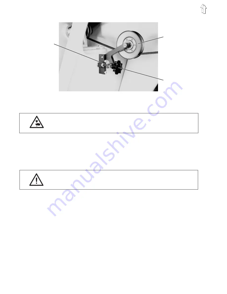
The tension pulley 2 on the V-belt determines the stitch length.

The belt adjustment gearing on the motor is changed by the tension. A
stitch length of 1.8 mm is set at the factory.

Caution Risk of Injury !

Turn the main switch off.
Change the stitch length only with the sewing unit turned off.

Loosen lock nut 1.

Turn the star knob 3.

Shorter stitches

= Tension pulley lower

Longer stitches

= Tension pulley higher

Tighten the lock nut 1.

ATTENTION !

After a stitch length change the following points must be observed.

The performance of the sewing unit has changed.

The position of the sew-on point has changed.

Set the seam beginning again !

If the positions of the sew-on points of the right and left clamping
tables do not agree, then the stitch length has been set differently.

Set the stitch length again !

2

3

1

32

Содержание 975-1-5

Страница 1: ...5 1 Pressure Foot Pressure 13 2 5 2 Height Adjustment Range 14 2 5 3 Timing of the Pressure Foot Movement 15 2 6 Thread Controller Spring 16 2 7 Thread Tension Opening 17 2 8 Lubrication 18 2 8 1 Regulating the Lubrication 19 2 9 Sewing Arm 21 2 9 1 Position of the Sewing Arm 21 2 9 2 End Position Dampening of the Cylinder 22 2 9 3 Timing of the Operation of the Switches 23 2 10 Adjustment Screws ...

Страница 2: ... 4 2 Position of the Switching Disks on the Shaft 37 4 5 Position of the Clamping Tablees 38 4 6 Fixed Clamp 39 4 7 Swing Clamps 41 4 7 1 Renewing the Coatings on the Swing Clamps 43 4 8 Interior Slides 44 4 8 1 Setting the Interior Slides 45 4 9 Side Slides 47 4 10 Outer Forward Slide 48 4 11 Center Forward Slide 49 4 12 Inner Forward Slide 50 4 13 Hold down 52 5 Causes of Unequal Edge Intervals ...

Страница 3: ...e Instructions may only be carried out by specialists or appropriately trained personnel Caution Risk of Injury During repair conversion and maintenance work turn the main switch off Adjustment work and function testing with the machine running may only be conducted with greatest caution under strictest observence of all safety measures 3 ...

Страница 4: ... to 44 and press the STOP key The sewing head is lowered Turn the needle bar into the lowest position with the handwheel With the block 2 press the gauge 1 against the needle bar bushing Tighten screw 3 Pull out the gauge and turn the handwheel in the direction of run until the block touches the needle bar bushing In this position the hook point must be at the center of the needle Loosen screws 4 ...

Страница 5: ...er the sewing head Set the program switch to 44 and press the STOP key The sewing head is lowered Needle bar height Bring the needle bar into the looping stroke position with the handwheel Loosen screw 1 Move the needle bar The center of the furrow must lie at the hook point 2 Tighten screw 1 Clearance to the hook point Loosen screws 3 and 5 Axially slide the hook 4 on the shaft The clearance betw...

Страница 6: ...th this function sequence the cut off end of the needle thread is pulled out of the area of the needle plate before this has a chance to clamp the thread 2 3 1 Lateral Position of the Needle Plate Carrier The needle should enter the needle hole of the raised needle plate centered Caution Risk of Injury Turn the main switch off Adjust the position only with the sewing unit turned off Remove the oil...

Страница 7: ...g head is lowered Loosen the lock nut and adjust the stop screw 3 The clearance between the upper edge of the needle plate 1 and the lower edge of the pin 2 is 27 7 mm Tighten the lock nut Lower Position Remove the oilpan Set the program switch to 44 and press the STOP key The sewing head is lowered and the needle plate and pressure foot are raised Press the START key With the Σ key the sewing hea...

Страница 8: ...greatest possible caution Upper position switch Set the program switch to 63 and press the STOP key Set the program switch to 20 Bring the needle plate manually into the lower position The display must show b20 If not the switch position must be corrected Lower position switch Set the program switch to 63 and press the STOP key Set the program switch to 19 Bring the needle plate manually into the ...

Страница 9: ...he sewing head needle plate and pressure foot can now be raised and lowered again as often as desired The needle plate should move up quickly but not with a jerk If not then the throttle 1 must be set again Needle plate down speed Set the throttle 2 Conduct a function test Set the program switch to 44 and press the STOP key The sewing head the needle plate and the presser foot will be lowered Pres...

Страница 10: ...n False setting can have the following effects Thread breakage Eyes on the reverse of the cloth Loud noises 2 4 1 Height of the Finger The finger 1 should be at the same height as the nose of the middle piece Caution Risk of Injury Conduct adjustment work and function testing only with greatest possible caution Lower the sewing head Set the program switch to 44 and press the STOP key The sewing he...

Страница 11: ...hindered between the finger and middle piece Caution Risk of Injury Conduct adjustment work and function testing only with greatest possible caution Lower the sewing head Set the program switch to 44 and press the STOP key The sewing head is lowered and the needle plate and pressure foot raised Opening gap Loosen screw 2 Alter the position of the finger 1 Tighten screw 2 Depth Loosen screw 2 Alter...

Страница 12: ...atest possible caution Lower the sewing head Set the program switch to 44 and press the STOP key The sewing head is lowered and the needle plate and pressure foot raised Loosen screw 3 With the handwheel bring the needle bar 1 mm behind the upper dead center seen in the direction of run Turn eccentric 4 until the finger is at the forward reversing point The middle piece 2 must be completely open T...

Страница 13: ...curs at the same time as the opening of the beard clamp 2 5 1 Pressure Foot Pressure The pressure foot should follow the triggering mechanism during the downward movement Too low pressure foot pressure can lead to missing stitches Caution Risk of Injury Turn the main switch off Adjust pressure foot pressure only with the sewing unit turned off Set the pressure foot pressure with screw 1 1 13 ...

Страница 14: ...ot raised Loosen the wing nut 4 and arrest the lever 5 in the lowest position Loosen nut 1 Press bolt 2 down to the end of the slot Tighten nut 1 Pull lever 3 forward until the piston rod of the cylinder is run out completely With the handwheel bring the pressure foot into the low position Screw off the head cover 8 Loosen screw 6 Set the presser bar 7 The clearance between the pressure foot and t...

Страница 15: ...adjustment work and function testing only with greatest possible caution Lower the sewing head Set the program switch to 44 and press the STOP key The sewing head is lowered and the needle plate and pressure foot raised Remove plug 1 Loosen both screws on the stroke eccentric Turn the stroke eccentric 2 on the shaft The axial position may not be changed Tighten both screws on the stroke eccentric ...

Страница 16: ...he sewing unit turned off Run Turn the handwheel until the needle has entered the cloth up to the eye Loosen screw 5 With the bolt 4 turn the whole thread tension unit 3 The thread controller spring 2 must just have reached its lowest position Tighten screw 5 again Tension Loosen screw 5 Pull the thread tension unit 3 out Loosen screw 1 Adjust bolt 4 Tighten screw 1 again Reinsert the thread tensi...

Страница 17: ...only with the greatest possible caution Loosen screw 3 Displace the thread tension unit 2 axially With pin 1 pressed in the thread must be able to be manually pulled unhindered through the opened tension Tighten screw 3 again Function test Turn the main switch on Set the program switch to 64 and press the STOP key Set the program switch to 9 Press the O key The tread tension unit is opened by the ...

Страница 18: ...wer part of the sewing head where there is also the suction tube 3 with the metal filter Via this tube the pump 5 on the hook drive shaft sucks the oil back again Oil feed to the hook Along with the oil from the sewing head the pump 5 also sucks oil out of the oilpan This oil reaches the pump via a tube A rubber gasket prevents the tube end from lying directly on the bottom of the oilpan This avoi...

Страница 19: ...he sewing head lubrication The set oil quantity should be considerably greater than the actually required oil quantity The pump sucks the oil from the lowest point of the head back into the pan again Screw the head cover off Turn screw 2 completely in and then loosen by approx 1 2 of a turn Let the sewing unit run approx 2 minutes Hold a piece of paper between the presser bar and the cast wall Let...

Страница 20: ...with a smallest possible amount of oil so that a little oil as possible is consumed Turn screw 1 completely in and then loosen by approx 1 8 turn Let the sewing unit run approx 2 minutes Hold a piece of paper under the hook Let the sewing unit run at intervals and check if sufficient oil is being spun off onto the paper If not then adjust screw 1 accordingly Increase the quantity of oil Turn screw...

Страница 21: ...n Lower position Remove the feed plate 4 Lower the sewing head Set the program switch to 44 and press the STOP key The sewing head is lowered and the needle plate and pressure foot raised Loosen screw 2 and turn piston rod 3 With lowered sewing arm 1 the clearance between the milled bottom of the sewing arm and the lower arm surface should be 72 5 mm Tighten screw 2 Upper position The upper positi...

Страница 22: ...eedle plate and pressure foot raised Press the START key With the Σ key the sewing head can now be raised and lowered again as often as desired The sewing head should run softly into the end position If not then throttle 2 must be reset End position dampening lower sewing head Adjust throttle 1 Conduct a function test Set the program switch to 44 and press the STOP key The sewing head is lowered a...

Страница 23: ...nually into the upper position The display must show b17 If not then the switching point switch 1 must be adjusted Adjust bushing 4 switching point The bushing 4 should in this position have approx 5 mm clearance from the plate Lower switch position b18 Set the program switch to 63 and press the STOP key Set the program switch to 18 Bring the sewing head manually into the lower position The displa...

Страница 24: ... testing only with greatest possible caution Switch upper position Set the program switch to 44 and press the STOP key The sewing head is lowered Loosen screw 2 and set the lever with the contact roller 1 Thereby lightly press the contact roller 1 onto the belt Tighten screw 2 again Repeat the procedure with the 2nd contact roller The belt must run easily If not then the two contact rollers must b...

Страница 25: ...read fall behind the thread pull hook of the knife When the drive segment is pressed out of the guide curve recess then both threads are pulled to the counter knife and cut shortly before the thread lever high position When the thread lever high position and thereby the 2nd position are reached the motor stops The magnet for the thread tension opening is turned off and the magnet for the thread tr...

Страница 26: ...ate Remove the hook Loosen screws 3 and 4 Loosen the hex head bolt 2 Place gauge 5 on the shaft Press the base plate 1 up against the gauge Tighten screws 3 and 4 Tighten the hex head bolt 2 Gauge Order no 396 351050 Guide curve Turn the handwheel until the needle 6 lies approx 2 mm above the top edge the needle plate 7 Loosen the screw Turn guide curve 8 The drive segment should touch the guide c...

Страница 27: ...ance only with the sewing unit turned off Loosen screw 2 Turn the magnet anchor 1 The clearance between the drive segment 4 and guide curve 3 should be 0 2 mm Tighten screw 2 Note With too much play the thread pull knife cannot swing far enough to the back and not capture the threads At this setting the function of the spring 5 in the drive segment and the easy movement of the drive segment 4 shou...

Страница 28: ...d pull knife and counter knife only with the sewing unit turned off Counter knife Loosen screw 4 Set the clearance The clearance between needle and counter knife 2 is 4 mm Tighten screw 4 Thread pull knife Turn the handwheel until the thread lever is in its highest position Loosen screws 5 and 6 Set the position of the thread pull knife 3 The blades should be overlapped 0 5 mm The tip of the threa...

Страница 29: ...r knife pressure only with the sewing unit turned off Counter knife pressure Loosen screw 1 Swing the carrier 2 with counter knife Tighten screw 1 Conduct a check Place a thread behind the pulling hook of the swung back thread pull knife Swing the thread pull knife manually to the counter knife If the thread is not cut flawlessly the counter knife pressure must be reset 2 1 29 ...

Страница 30: ...sewing head collides with the clamp Maximum sewing length not possible 2 Slow sewing Time loss Unequal seam interval 3 Opening the beard clamp Unequal seam interval Lower the pressure foot Seam run not squared off Beard clamp collides with the pressure foot Tearing of the cloth Missing stitches 4 Stop the sewing cycle Bartacking too short Bartacking too long 5 Bring the folding device Insignifican...

Страница 31: ...ched when the direction of movement of the clamping table no longer changes Switching point 5 results from the length of the strip Mark the delay distances on the guide curve Because of the reaction times the signals must be triggered earlier accordingly Points 1 2 6 Delay distance approx 20 mm Points 3 4 Delay distance approx 10 mm Cut the strip to size 1 to 2 appropriate to the marking taking de...

Страница 32: ...d off Loosen lock nut 1 Turn the star knob 3 Shorter stitches Tension pulley lower Longer stitches Tension pulley higher Tighten the lock nut 1 ATTENTION After a stitch length change the following points must be observed The performance of the sewing unit has changed The position of the sew on point has changed Set the seam beginning again If the positions of the sew on points of the right and lef...

Страница 33: ... inner and outer curve runs 1 a Outer guide curve i Inner guide curve Guide Curve Function No 1 outer Side slides Fixed table forward and back No 1 inner Outer forward slide forward and back No 2 outer Center forward slide and side slides Swing table forward and back No 3 outer Sleeve table up and down No 3 inner Swing table turn forward and back 1 33 ...

Страница 34: ...unit turned off Bring the folding device of the clamping tables into the base position Screw the setting disk 4 onto the shaft 3 Align the setting disk so that the 0 position agrees with the edge 2 of the mounting plate for the valves Set the program switch to 40 and press the STOP key Turn the shaft with the guide curves using the REPEAT key At 20 the forward movement of the side slides of the fi...

Страница 35: ...te stop E 261 Remove the cloth Bring the folding device of the clamping table into the base position Cut the aluminium strips to size A 80 mm B C D E 15 mm Screw the setting disk 4 onto the shaft 3 Align the setting disk so that the 0 position agrees with the edge 2 of the mounting plate for the valves Set the program switch to 40 and press the STOP key Turn the shaft with the guide curves into th...

Страница 36: ...p and sleeve clamp of the fixed table close full pressure close half pressure open and pressure free No 4 Swing clamp open and close No 5 Sleeve clamp of the sleeve table open and close No 6 Hold down hold open and closed No 7 and 8 Interior slides forward and back No 9 and 10 Trim clamp cylinder for swing clamp open and close Cross clamp cylinder for swing clamp Piston rod run in Cylinder pressur...

Страница 37: ...ted Hold down back No 8 163 Valve operated Interior slides operated No 10 232 Valve released Cross clamp cylinder has full pressure Bring the folding device of the clamping table into the base position Screw setting disk 3 onto the shaft 2 Align the setting disk so that the 0 position agrees with the edge 1 of the mounting plate for the valves Set the program switch to 40 and press the STOP key Wi...

Страница 38: ...e so that the clearance of the short side seam is 1 mm The smaller the edge interval is to be the farther the clamping table must be distanced from the machine head Tighten the lock nuts Tighten screws 2 3 and 5 The two clamping plates are present at each clamping table The setting is to be made with both clamping plates Conduct a function test with low cutting rpm Set the program switch to 41 and...

Страница 39: ...earance to the rotation axis is 0 5 mm It is set at the factory with a gauge and may not be altered Height of the fixed clamp Remove the swing clamp 2 clamping table left Loosen the lock nut and turn the adjustment screw 3 The fixed clamp should be 3 mm higher in the forward area than in the rear area Reinstall the swing clamp again Set the adjustment screw During sewing the fixed clamp should hav...

Страница 40: ...e the chrome foil 4 on the Delrin 5 should prevent the cloth from being pulled out of the clamp during sewing Pull off damaged Delrin 5 with the chrome foil 4 Cut strips from the chrome foil and Delrin In the same widths as before Clean the adhesive surfaces Affix the Delrin 5 to the fixed clamp The Delrin should end in line with the inner side of the fixed clamp Cut 2 mm wide antislip foil 3 and ...

Страница 41: ...e to the fixed clamp is 1 mm The clearance is set in the base position of the folding device Loosen the screws 4 Turn the eccentric bushings 2 one each right and left The eccentric bushings must be set tight Tighten the screws 4 Height of the closed swing clamp The swing clamp should press the fixed clamp downward In all seam segments the clearance to the needle plate should be 0 5 mm Loosen lock ...

Страница 42: ...clamp cylinder When the folding device has reached the sewing position the trim clamp cylinder 4 presses the swing clamp in the rear area downward against the fixed clamp Loosen screws 6 Alter the position of the cylinder holder 5 appropriately Tighten screws 6 again Speed when opening and closing Set the program switch to 41 and press the STOP key With the REPEAT key run through the function sequ...

Страница 43: ...mm width and affix to the sponge rubber The antislip foil should end in line with the outer side of the swing clamp Remove the antislip foil 1 and Delrin 2 from the swing clamp 6 Cut the Delrin 2 to size as before and affix to the swing clamp 6 Cut the antislip foil 1 to size as before and affix to the Delrin Beard clamp Remove damaged antislip foil 7 from the beard clamp 8 Cut antislip foil 7 to ...

Страница 44: ...d table f 1 Interior slides Fixed table In order that the interior slides during their movement into the initial position do not pull the folded trim with them the inner forward slide 3 in this phase must still be in the extended position The inner forward slide is thus brought into the initial position 2 later The clearance between seam and trim edge is a and b 1 mm f 1 5 mm ATTENTION Scratches c...

Страница 45: ...he clearance of the trim edge b to the pointed seam is 1mm Loosen nut 2 Align the interior slide parallel to the swing clamp Tighten nut 2 again Loosen screws 3 Set the interior slide so that this extends sideways 1 5 mm relative to the swing clamp Tighten screws 3 again Loosen screws 1 Set the interior slide so that this extends forward 1 5 mm relative to the swing clamp Tighten screws 1 again AT...

Страница 46: ... is to be checked and possibly to be corrected The interior slides must be run back in the sewing position and in the removal position Bring the folding device into sewing position Loosen lock nut 4 Turn the extension 5 The run back interior slide of the fixed table should have a clearance of 2 mm to the fixed clamp in the sideways direction Tighten lock nut 4 again The extended piston rod of the ...

Страница 47: ...his position not being folded around the side slides with sharp edges Slightly variing edge intervals on the side seam cannot be avoided Caution Risk of Injury Turn the main switch off Set the side slides only with the sewing unit turned off Conduct a function test with the greatest possible caution Loosen screws 3 Align the side slides 2 The swung completely forward side slides should have a clea...

Страница 48: ...a function test with the greatest possible caution Clearance to the interior slide Loosen lock nut 3 Set the tie rod 2 The outer forward slide should in its initial position have a clearance of 1 to 2 mm to the interior slide Tighten lock nut 3 Sideways position Loosen screw Align the position of the outer forward slide on the carrier Tighten the screws Conduct a function test Set the program swit...

Страница 49: ...he inner forward slide runs back into the initial position Caution Risk of Injury Turn the main switch off Set center forward slide only with the sewing unit turned off Conduct a function test with the greatest possible caution Setting the position Loosen screws 2 Align the center forward slide Tighten screws 2 again Conduct a function test Set the program switch to 41 and press the STOP key With ...

Страница 50: ...reatest possible caution Setting the position of the edge Loosen screws 2 and 3 Align the position of the inner forward slide with the carrier 8 The trim edge should have a clearance of 1 mm to the pointed seam Tighten screws 2 and 3 again Setting the position of the run forward forward slide Loosen screw 4 Set eccentric 5 The front edge of the inner forward slide should lie at the same height as ...

Страница 51: ... of the swing clamp and of the interior slide Turn the setting wheel 2 into position 1 Bend the inner forward slide Speed of the forward slide forward and back Set the program switch to 41 and press the STOP key With the REPEAT key run through the function sequence in interval operation Observe the movement of the inner forward slide The slide should move quickly but not jerk Set the movement with...

Страница 52: ...3 Set the position of the hold down by relocating the stop 4 There should be a clearance of 2 to 3 mm between the casing of the hold down and the side slides Tighten screws 3 again Setting the speed Set the program switch to 41 and press the STOP key With the REPEAT key run through the function sequence in interval operation Observe the movement of the hold down The hold down should move quickly b...

Страница 53: ...uses for unequal edge intervals are listed in the following table Possible Causes of Unequal Edge Intervals Possible Cause Effect on Edge a b c d e f Folding Device Position of the interior slides Position of the inner forward slide Position of the clamping table Interior slides scratched Position of the side slides Position of the hold down Inner forward slide run too far in Center forward slide ...

Страница 54: ...e wrong position Machine Head Needle thread tension too high Stitch length too great Sewing speed house shaped seam cutting rpm too high Height of the needle plate too high Pressure foot stroke position too low Guide Curve Position and length of the aluminium strips wrong Trim Blanks Size of the blank wrong Trim incorrectly inserted has an effect on the edge has no effect on the edge 54 ...

Страница 55: ...ly Setting the 1st position Turn the handwheel 3 until the guide curve 6 has reached the position shown in the picture Set disk 4 accordingly Check that both threads are being cut correctly Correct the position of the disk if necessary Setting the 3rd position Turn the handwheel 3 until the thread lever high position is reached Set disks 1 and 2 according to the sketch The flank of the 3rd positio...

Страница 56: ...ressures drops below 4 2 bar Caution Risk of Injury Set the compressed air monitor with the sewing unit turned off and with the greatest possible caution Pull up the knob 1 and reduce the operating pressure until the pressure monitor turns the sewing unit off The maintenance unit should show a pressure of 4 2 bar If the value shown is greater or smaller reset the pressure monitor with the screw 2 ...

Страница 57: ...ate hook and thread trimmer Check the oil level in the oilpan Check the oil feed at the window Check hook lubrication Check the timing belt Drive Unit for the Machine Head and Guide Curve Check the ventilator wheel on the motor Check the condition and tension of the V belt Guide Curve Lubricate the curve paths with liquid grease Lubricate the roller Clamping Table Clean the running surfaces of the...

Отзывы: