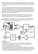
Setting Up
Remove the case lid.
Turn the TDS1 on. Check the green power light illuminates continuously.
Check the Active light flashes, once for AUTOmatic, twice for MANual. This
confirms the microprocessor is running.
Play a CD at normal volume over the PA system.
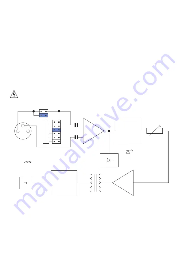
Adjust the attenuator settings until the internal green light (LED 5 immediately
behind the input XLR socket) flashes (weakly) in time with the CD audio signal. If
the signal is too small, move the attenuator link one position eg from J5 to J6 (or
J7 to J8 etc) until the light flashes. With a very small input signal such as a
1
2
3
Telephone
Interface
Circuit
Compressor
VR1
Send Level
J2
J1
Connected to
Case Only
XLR Socket
Audio Input
LED 5 Compressor
Control Signal
J5
J10
A
tt
e
n
u
a
to
r
Telephone
Line
Isolation Barrier
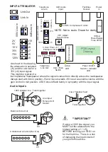
Start by wiring in the audio feed cable and terminate with a male 3 pin XLR plug.
Wire the XLR plug according to the type of input signal as shown. Note that pin 1
of the XLR connects to the case of the TDS1 unit and should be grounded at the
source end.
The TDS1 has a balanced 3 wire audio input which allows it to work remotely,
without electrical interference, even with long lengths of feed cable attached. You
can use an unbalanced low level 2 wire feed (eg record out), but keep the feed
cable short (<2m) to avoid hum and noise interference. Unbalanced inputs should
have pins 1 and 3 connected together and both of these connect to the screen
(braid) of the incoming audio feed cable.
The signal source can be any line level signal from 0.5V up to a 100V line
speaker feed. Taking the output from the terminals of a loudspeaker will also
work, though you will need a much lower attenuator setting (around 15V).
WARNING It is possible to get an electric shock from a 100V speaker line
during peak audio output. Switch the PA system off to prevent the risk of
electric shock when making connections.


