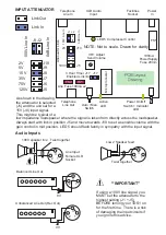
TDS1 Facilities Output
The facilities socket is for advanced users who want to extend the capabilities of the
TDS1. It enables remote AUTO / MAN switching and allows a remote Active light to
be used. The remote light can be very useful to indicate the TDS1 is in use and
connected. Pin1 is normally configured as an additional remote LED output.
However it can be wired as a remote start to special order. The remote start (switch
to 0V) can be used to start a messaging service or recorded announcement
message or even as an on/off switch.
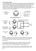
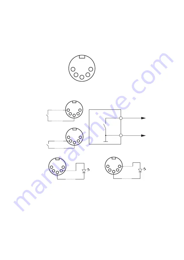
Pin Description
1
Remote LED/Start
2
0V
3
Remote AUTOmatic
4
Remote LED
5
Remote MANual
Facilities Wiring Diagrams
Close switch to
enable
AUTOmatic
mode
Press switch to
Hold / Release
a MANual call
NOTES
Pin 2 (0V connection). To make it easier to connect multiple return wires to pin
2, solder a thick length of wire onto the pin to extend it by 10-15mm. Solder the
returns onto this thick wire. Insulate connections to prevent short circuits
between pins.
Use a fine tipped soldering iron to make connections. Whilst short circuited
connections are unlikely to damage your TDS1, they certainly won’t help
matters! Check all connections thoroughly and insulate between pins.
Ensure that the switch on the TDS1 is set to the centre MANual position if you
wish to use remote switching. (Otherwise the remote AUTOmatic mode will not
work).
Remote Active
LED
0V
1
2
To remote
equipment
Remote Start equivalent circuit
(Available to special order)
TDS1
Facilities Socket is
a 5 Pin DIN
Connector
1
2
3
4
5
1
2
3
4
5
1
2
3
4
5
1
2
3
4
5
1
2
3
4
5


