background image

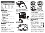
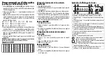
4. If the ‘P/Z’ terminal is programmed as an output, the output follows

the PGM programmed in Section [080]. A small relay, buzzer or
other DC operated device may be connected between the positive
supply voltage and the ‘P/Z’ terminal (maximum load is 50mA).

Applying Power

Once all wiring is complete, and the equipment is secured to the build-
ing structure with at least two screws apply power to the control panel:
1.  Connect the battery leads to the battery.
2.  Connect the AC transformer. 
For more information on control panel power specifications, see the
control panel Installation Manual.

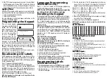
Programming the Keypad

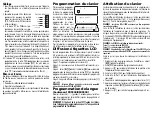
There are several program-
ming options available for the
keypad. These are described
below. Programming the key-
pad is similar to programming
the rest of the system. When
you are in the keypad pro-
gramming sections, the key-
pad will display which options
are turned on along the top of
the display.  To turn an option
on or off, press the number corresponding to the option on the number
pad. The numbers of the options that are currently turned ON will be
displayed.  For example, if options 1 and 4 are on, the display will
look like this on the different keypad displays:


For information on programming the rest of your security system,
please refer to your system’s Installation Manual.

Broadcasting LCD Labels

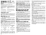
All LCD programming is done per keypad. If more than one LCD key-
pad is present on the system, labels programmed at one keypad can
be broadcast to all other LCD keypads. Perform the following procedure
in order to broadcast labels:
Step 1 - Program one LCD keypad completely.
Step 2 - Make sure all LCD keypads are connected to the Keybus.
Step 3 - Enter keypad programming by pressing [

,

][8][Installer

Code][

,

], then enter section [998] at the keypad that was pro-

grammed. The keypad will now broadcast all the information pro-
grammed to all the other LCD keypads on the system.
Step 4 - When the keypad is finished press the [#] key to exit.

NOTE: Label broadcast from this keypad is only compatible with other

PK5500 and RFK5500 Keypads.

Language Programming 

(PK5500\RFK5500 Only)

Hold (<>) keys for 2 seconds to enter language programming,
scroll to the desired language and Press [

,

] to select.

NOTE: If section [077] option 4 is OFF, language programming

can only be performed while in installers programming.

Enrolling the Keypad

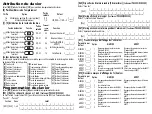
The keypad will need to be assigned to a partition and slot if supervi-
sion or keypad zones are being used.  Keypad assignments and key-
pad option programming must be done at each keypad individually.
The 1st digit of keypad assignment is used to determine partition
assignment (1 to 8).  If partitioning is not used, enter [1].  For Global
Keypads, enter [0].

NOTE: LED and ICON keypads cannot be programmed as Global Keypads

The 2nd digit of keypad assignment is used to determine slot assign-
ment for keypad supervision.  Each keypad will be assigned a different
slot number from 1 to 8.  PK5500 and RFK5500 LCD keypads come
defaulted in slot 8.  If LCD keypads are used one LCD keypad must
remain in slot 8.

NOTE: The RFK55XX enrolls as two modules:

Light 1 = keypad section of the RFK55XX

Light 17 = receiver section of the RFK55XX

NOTE: Deleting all wireless devices from the RFK55XX or defaulting the

RFK55XX will cause a supervisory fault.

Enter the following at each keypad installed on the system:
1. Enter Installer Programming by pressing [

,

][8][Installer’s Code]

2.  Press [000] for Keypad Programming
3.  Press [0] for Partition and Slot Assignment
4.  Enter the 1st digit (0 to 8 for partition assignment)
5.  Enter the 2nd digit (1 to 8 for slot assignment supervision)
6. Press the [#] key twice to exit programming.
7. After assigning all keypads, perform a supervisory reset by entering

[

,

][8][Installer’s Code][902] and wait for 60 seconds.

8. Press the [#] key to exit programming after 60 seconds.

Programming Labels 

(PK5500\RFK5500 Only)

1. Enter keypad programming by pressing [

,

][8][Installer Code][

,

].

Enter the 3-digit section number for the label to be programmed.

2. Use the arrow keys (<>) to move the underline bar underneath

the letter to be changed. 

3. Press the number keys [1] to [9] corresponding to the letter you

require. The first time you press the number the first letter will
appear. Pressing the number key again will display the next letter.

4. When the required letter or number is displayed use the arrow keys

(<>) to scroll to the next letter.

5. When you are finished programming the Zone Label, press the [

,

]

key, scroll to “Save,” then press [

,

].

6. Continue from Step 2 until all Labels are programmed.

NOTE: Label Programming can also be accessed from the [

,

][6] User

Functions Menu

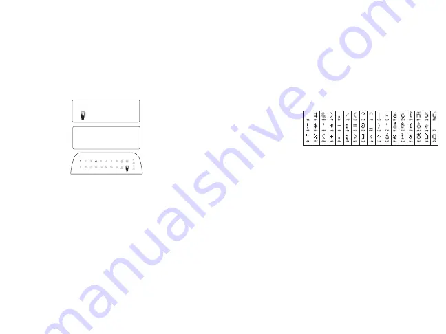
ASCII Characters

Changing Brightness/Contrast

LCD Keypads

1. Press [

,

][6][Master code].

2. Use the [<][>] keys to scroll to either Brightness Control or Contrast Control.
3. Press [

,

] to select the setting you want to adjust.

4. a) ‘Brightness Control’: There are multiple backlighting levels. Use the [<][>]

keys to scroll to the desired level.

5. b) ‘Contrast Control’: There are 10 different display contrast levels. Use the

[<][>] keys to scroll to the desired contrast level.

6. To exit, press [#].

LED/ICON Keypads

1. Press [

,

][6][Master Code].

2. Use the [>] key to move through the 4 different backlighting levels.
3. The level is automatically saved when you press [#] to exit.

Changing the Buzzer Level

LCD Keypads

1. Press [

,

][6][Master Code].

2. Use the [<][>] keys to scroll to Buzzer Control.
3. There are 21 different levels, use the [<][>] keys to scroll to the desired level.
4. To exit, press [#].

LED/ICON Keypads

1. Press [

,

][6][Master Code].

2. Use the [<] key to move through the 21 different buzzer levels.
3. The level is automatically saved when you press [#] to exit.

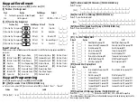
Toggle Option

1 _  _  4  _  _  _  _ 

[1]

 - A, B, C, 1

[4]

 - J, K, L, 4

[7]

 - S, T, U, 7

[0]

 - Space

[2]

 - D, E, F, 2

[5]

 - M, N, O, 5

[8]

 - V, W, X, 8

[3]

 - G, H, I, 3

[6]

 - P, Q, R, 6

[9]

 - Y, Z, 9,0

Содержание PK5500

Страница 1: ...n het systeem voor informatie over beperkingen m b t productgebruik en functie en informatie over de beperkingen m b t aansprakelijkheid van de fabrikant OPMERKING Deze instructies dienen te worden gebruikt in combinatie met de installatiehandleiding van het systeem van de centrale waarmee deze apparatuur gebruikt wordt ATTENZIONE Fare riferimento al manuale di installazione del sistema per avere ...

Страница 2: ...tamper hole on backplate 4 Remove keypad from hooks Place keypad into backplate ensure the wire is pushed back into the wall as much as possible Route the wire inside the keypadensuringhigh components are avoided Snapthe front assem bly closed ensuring that there is no pressure to the keypad from the wire below NOTE If any tension found between the front keypad assembly and wiring please open the ...

Страница 3: ...obal Keypads The 2nd digit of keypad assignment is used to determine slot assign ment for keypad supervision Each keypad will be assigned a different slot number from 1 to 8 PK5500 and RFK5500 LCD keypads come defaulted in slot 8 If LCD keypads are used one LCD keypad must remain in slot 8 NOTE The RFK55XX enrolls as two modules Light 1 keypad section of the RFK55XX Light 17 receiver section of th...

Страница 4: ...operate this equip ment FCC Compliance Statement Caution Changes or modifications not expressly approved by Digital Security Controls could void your authority to use this equipment This equipment generates and uses radio fre quency energy and if not installed and used prop erly in strict accordance with the manufacturer s instructions may cause interference to radio and television reception It ha...

Страница 5: ...Away Arm 12 User Functions 23 Bypass Recall 32 Partition 8 Select 05 No Entry Arm 13 Command Output 1 24 Bypass Group Recall 06 Chime On Off 14 Command Output 2 26 Time Date Program 07 System Test 16 Quick Exit 27 Partition 3 Select Section Zone Label 001 to 064 1 to 64 I_____I_____ I_____I_____I__ ___I_____I___ __I _____I_____ I_ ____I_____I__ ___I_____I____ _I I_____I_____ I_____I_____I__ ___I__...

Страница 6: ...lways Displayed When Armed Alarms not Displayed When Armed OFF I____I 8 Low Temperature Warning Enabled Low Temperature Warning Disabled Section Partition Label 101 to 108 1 to 8 I_____I__ ___I_____I____ _I_____I_____ I_ ____I _____I__ ___I_____I____ _I_____I_____I_ ____I I_____I__ ___I_____I____ _I_____I_____ I_ ____I _____I__ ___I_____I____ _I_____I_____I_ ____I For Partition 1 Command O P 1 to ...

Страница 7: ...lly NOTE When batteries in one device need to be replaced the bat teries in all devices should be replaced at the same time Troubleshooting 1 When I enter the 2 digit zone number when adding a wireless device the keypad gives me a long beep Youcannotenter ESNs unlesstheRFK55XXis properly connectedto the Keybus 2 I have entered the ESN for the device but when I violate the device the zone does not ...

Страница 8: ..._____I_ ____I_____I___ __I 49 Key 9 I_____ I_____I_____I__ ___I_____I____ _I 42 Key 2 I____ _I_____I_____I_ ____I_____I___ __I 50 Key 10 I_____ I_____I_____I__ ___I_____I____ _I 43 Key 3 I____ _I_____I_____I_ ____I_____I___ __I 51 Key 11 I_____ I_____I_____I__ ___I_____I____ _I 44 Key 4 I____ _I_____I_____I_ ____I_____I___ __I 52 Key 12 I_____ I_____I_____I__ ___I_____I____ _I 45 Key 5 I____ _I___...

Страница 9: ... située sous la charnière de porte et poussez le tournevis vers le mur Montage et câblage du clavier 1 Fixez le clavier à l aide des trous de montage Utilisez les 4 vis four nies à moins de faire le montage sur une seule boîte électrique 2 Placez le clavier sur les crochets de la plaque arrière et faites bas culer vers le bas pour engager 3 Faites passez les fils dans la fente de câblage ou dans l...

Страница 10: ...gardé automatiquement lorsque vous appuyez sur pour sortir Changement de volume du résonateur Clavier LCD 1 Tapez 6 code maître 2 Utilisez pour faire défiler jusqu au niveau de sonorité désiré 3 Appuyez sur pour faire votre sélection 4 Appuyez sur pour sortir Claviers LED ICON 1 Tapez 6 code maître 2 Utilisez la touche pour faire défiler les 21 niveaux d indicateur sonore 3 Le niveau est sauvegard...

Страница 11: ...ande 4 32 Partition 8 Sélectionnez 09 Mode trouble 22 Surveillance caméra activée Section Zone Label 001 064 1 64 I_____I___ __I_____I_____ I_ ____I_____I__ ___I _____I____ _I_____I_____I_ ____I_____I___ __I I_____I___ __I_____I_____ I_ ____I_____I__ ___I _____I____ _I_____I_____I_ ____I_____I___ __I 065 I_____I___ __I_____I____ _I_____I_____I__ ___I _____I___ __I_____I_____ I_____I_____I__ ___I I...

Страница 12: ...er un dis positif sans fil le clavier émet un bip long Les numéros ESN peuvent être saisis seulement quand un récepteur sans fil RFK55XX est connecté au Keybus Voir la section 2 pour les instructions sur la configuration et câblage du module RFK55XX 2 J ai saisi le numéro ESN pour le dispositif mais quand j ai violé le dispositif la zone n est pas apparue comme ouverte sur le clavier Vérifier le s...

Страница 13: ... diffusés à tous les autres cla viers ACL Suivez la démarche suivante pour diffuser les intitulés Étape 1 Programmez complètement un clavier ACL Étape 2 Assurez vous que tous les claviers ACL sont connectés sur le KEYBUS Étape 3 Entrez 8 code de l installateur pour accéder à la programmation du clavier puis dans la section 998 au clavier déjà programmé Le clavier diffusera tous les renseignements ...

Страница 14: ...autre garantie ou responsabilité concer nant le présent produit En aucun cas Digital Security Controls ne pourra être tenue respon sable des conséquences directes ou indi rectes de dommages relativement à la perte de profits prévus à la perte de temps ou à toute autre perte subie par l acheteur en rap port avec l achat l installation et le fonctionne ment ou la défaillance du présent produit AVERT...

Страница 15: ... la température locale activé Affichage de la température locale désactivé MARCHE I____I 6 Message guide des options de suspension MARCHE Message guide des options de suspension ARRÊT ARRÊT I____I 7 Pour utilisation future ARRÊT I____I 8 Défilement automatique zones ouvertes activé Défilement automatique zones ouvertes dés activé Paramètre par défaut Option MARCHE ARRÊT MARCHE I____I 1 Carillonpou...

Страница 16: ...I_____I___ __I 49 Clé 9 I_____ I_____I_____I__ ___I_____I____ _I 42 Clé 2 I____ _I_____I_____I_ ____I_____I___ __I 50 Clé 10 I_____ I_____I_____I__ ___I_____I____ _I 43 Clé 3 I____ _I_____I_____I_ ____I_____I___ __I 51 Clé 11 I_____ I_____I_____I__ ___I_____I____ _I 44 Clé 4 I____ _I_____I_____I_ ____I_____I___ __I 52 Clé 12 I_____ I_____I_____I__ ___I_____I____ _I 45 Clé 5 I____ _I_____I_____I_ _...

Страница 17: ...deur scharnier bevindt en draai de schroevendraaier Het toetsenbord bevestigen en de bedrad ing aanbrengen 1 Maak het toetsenbord aan de muur vast door middel van de montage gaatjes Gebruik alle 4 bijgeleverde schroeven tenzij u het toestel monteert op een enkele wandcontactdoos 2 Bevestig het toetsenbord aan de haakjes op de achterplaat en klik het dicht met een neerwaartse beweging 3 Leid de kab...

Страница 18: ...e dure uit om de labels te versturen Stap 1 Programmeer één LCD toetsenbord volledig Stap 2 Zorg dat alle LCD toetsenborden op de keybus zijn aangeslo ten Stap 3 Ga naar toetsenbordprogrammering door te drukken op 8 Installateurscode en voer deel 998 in op het toetsen bord dat geprogrammeerd is Het toetsenbord verstuurt nu alle gepro grammeerde informatie naar alle andere LCD toetsenborden op het ...

Страница 19: ...de toetsen om naar het gewenste niveau te bladeren 4 Om te verlaten druk op LED ICON toetsenborden 1 Druk op 6 Master Code 2 Gebruik de toets om door de 21 verschillende zoemerniveaus te bladeren 3 Het niveau wordt automatisch opgeslagen wanneer u op drukt om te ver laten Symboles d affichage du clavier 1 A B C 1 4 J K L 4 7 S T U 7 0 Space 2 D E F 2 5 M N O 5 8 V W X 8 3 G H I 3 6 P Q R 6 9 Y Z 9...

Страница 20: ...m in haar naam op te tre den om deze garantie te wijzigen of aan te pas sen noch namens haar enige andere garantie of aansprakelijkheid met betrekking tot dit product op zich te nemen Digital Security Controls kan onder geen enkele omstandigheid verantwoordelijk worden gehouden voor directe indirecte of gevolg schade verlies van verwachte winst verlies van tijd of enige andere verliezen die optred...

Страница 21: ...ndo uitgang 1 24 Terugroeping omleidingsgroep 06 Bel aan uit 14 Commando uitgang 2 26 Programmering tijd datum 07 Systeemtest 16 Snelle uitgang 27 Partitie 3 selecteer Deel Zone Label 001 064 1 64 I_____I__ ___I_____I____ _I_____I_____ I_ ____I _____I__ ___I_____I____ _I_____I_____I_ ____I I_____I__ ___I_____I____ _I_____I_____ I_ ____I _____I__ ___I_____I____ _I_____I_____I_ ____I 065 I_____I___ ...

Страница 22: ...eratuurweergave OFF Aan I____I 6 Omleidingsopties prompt ON Omleidingsopties prompt OFF Uit I____I 7 Voor toekomstig gebruik Uit I____I 8 Automatisch schuiven open zones ON Automatisch schuiven open zones OFF Standaard Optie Aan Uit Aan I____I 1 Bel ingeschakeld voor zoneopeningen Bel uitgeschakeld voor zoneopeningen Aan I____I 2 Bel ingeschakeld voor zonesluitingen Bel uitgeschakeld voor zoneslui...

Страница 23: ...MERKING Wanneer de batterijen in één apparaat vervangen moeten worden dient u tegelijkertijd de batterijen in alle appa ratuur te vervangen Probleemoplossing 1 Bij het invoeren van het tweecijferige zonenummer bij toevoegen van draadloze apparatuur geeft het toetsenbord een lange piep U kunt geen ESN s invoeren tenzij de RFK55XX juist is aangesloten op de keybus 2 Ik heb het ESN voor het apparaat ...

Страница 24: ...__I 49 Sleutel 9 I_____ I_____I_____I__ ___I_____I____ _I 42 Sleutel 2 I____ _I_____I_____I_ ____I_____I___ __I 50 Sleutel 10I_____ I_____I_____I__ ___I_____I____ _I 43 Sleutel 3 I____ _I_____I_____I_ ____I_____I___ __I 51 Sleutel 11I_____ I_____I_____I__ ___I_____I____ _I 44 Sleutel 4 I____ _I_____I_____I_ ____I_____I___ __I 52 Sleutel 12I_____ I_____I_____I__ ___I_____I____ _I 45 Sleutel 5 I____...

Страница 25: ... e girare il cacciavite Montaggio e cablaggio della tastiera 1 Fissare la tastiera alla parete utilizzando i fori di montaggio Impiegare tutte e 4 le viti fornite a meno che il montaggio avvenga su una scatola di connessione 2 Agganciare la tastiera alla piastra posteriore e muoverla verso il basso per innestarla 3 Posare i cavi attraverso la guida per cavi o i fori incompleti Collegare il Keybus ...

Страница 26: ...astiere LCD Per trasmettere le etichette eseguire la seguente procedura Passo 1 Programmare completamente una tastiera LCD Passo 2 Assicurarsi che tutte le tastiere LCD siano collegate al Key bus Passo 3 Entrare nella programmazione della tastiera premendo 8 Codice dell installatore quindi immettere la sezione 998 nella tastiera che è stata programmata La tastiera ora trasmet terà tutte le informa...

Страница 27: ...dice master 2 Usare i tasti per scorrere fino al Controllo cicalino 3 Sono disponibili 21 livelli diversi Usare i tasti per impostare il livello desiderato 4 Per uscire premere Tastiere LED ICON 1 Premere 6 Codice master 2 Usare il tasto per spostarsi attraverso i 21 diversi livelli del cicalino 3 Il livello viene salvato automaticamente quando si preme per uscire Simboli del display della tastier...

Страница 28: ...esponsabil ità in relazione a eventuali suoi rappresentanti e non li autorizza a modificare o cambiare questa garanzia né ad assumere altre garan zie o responsabilità in relazione a tale prodotto In nessun caso Digital Security Controls sarà ritenuta responsabile per danni diretti indiretti o consequenziali perdita di profitti e di tempo o per qualunque altro danno subito dall acquirente in relazi...

Страница 29: ...Stay Away 30 Seleziona partizione 6 07 Prova del sistema 19 Uscita comando 3 31 Seleziona partizione 7 08 Modalità bypass 21 Uscita comando 4 32 Seleziona partizione 8 09 Visualizzazione anomalie 22 Attiva telecamera Sezione Zona Etichetta 001 064 1 64 I_____I_____ I_____I_____I__ ___I_____I___ __I _____I_____ I_ ____I_____I__ ___I_____I____ _I I_____I_____ I_____I_____I__ ___I_____I___ __I _____I...

Страница 30: ...o disabilitato OFF I____I 5 Visualizzazione locale dellatemperatura ON Visualizzazionelocaledellatemperatura OFF ON I____I 6 Opzioni bypass prompt ON Opzioni bypass prompt OFF OFF I____I 7 Per uso futuro OFF I____I 8 Scorrimento automatico zone aperte ON Scorrimento automatico zoneaperte OFF Default Opzione ON OFF ON I____I 1 Chime abilitato per aperture zone Chime disabilitato per aperture zone O...

Страница 31: ... sostituire le batterie in un dispositivo le batterie di tutti i dispositivi devono essere sostituite allo stesso tempo Risoluzione dei problemi 1 Quando inserisco il numero di zona di 2 cifre durante l aggiunta di un dispositivo senza fili la tastiera emette un lungo bip Non è possibile inserire ESN se la tastiera RFK55XX non è colle gata correttamente al Keybus 2 Ho inserito l ESN relativo al di...

Страница 32: ... _I_____I_____I_ ____I_____I___ __I 49 Tasto 9 I_____ I_____I_____I__ ___I_____I____ _I 42 Tasto 2 I____ _I_____I_____I_ ____I_____I___ __I 50 Tasto 10 I_____ I_____I_____I__ ___I_____I____ _I 43 Tasto 3 I____ _I_____I_____I_ ____I_____I___ __I 51 Tasto 11 I_____ I_____I_____I__ ___I_____I____ _I 44 Tasto 4 I____ _I_____I_____I_ ____I_____I___ __I 52 Tasto 12 I_____ I_____I_____I__ ___I_____I____ ...

Отзывы: