7/ 22
5. COMPONENTS
5.1
FIXED DELIVERY PUMPING ELEMENTS
The pump has two fixed delivery standard pumping elements (200 cm^3/ min for each pumping element). A piston slides inside
the body of the pumping element coupled to the latter by a lapping process. The seal between the piston and the pumping body
is of a dry type, with no gasket provided between the two. The pumping element retention valve is of the tapered seal type. This
solution is able to guarantee an optimum seal for the system at high operating pressures (max. pressure of 400 bar). The
pumping elements are assembled on the manifold unit with a threaded attachment, which facilitates its assembly/ dismantling.
5.2
ENDLESS SCREW / WORM WHEEL UNIT
The pump has endless screw-worm wheel working kinematics with a transmission ratio of 1/40. The screw is made from special
steel with high mechanical resistance, which gives it optimum flexible rigidity. To guarantee high resistance to wear, the screw
has been subjected to Tenifer wear-resistant treatment. The screw is supported by oblique contact ball bearings, duly
preloaded, to reduce working clearance. The worm wheel is made of bronze alloy for gear systems, particularly suitable for
making the pump run quietly. The worm wheel shaft is made of special high resistance steel which gives the pump better
reliability and durability.
5.3
INVERTORS
CODE
DESCRIPTION
Series 0083420
Interchangeable electromagnetic inverter (mounted as standard on SUMO pump
Series 0083400
Electromagnetic inverter
Series 0083450
Electropneumatic inverter
SPARE PARTS
Code
Description
Current (A)
Power (W)
3150011
Electromagnet 24V DC
7
170
3150012
Electromagnet 110V AC 50/60 Hz
2
206
3150013
Electromagnet 230V AC 50/60 Hz
1
176
3133262
Seal kit
5.3.1
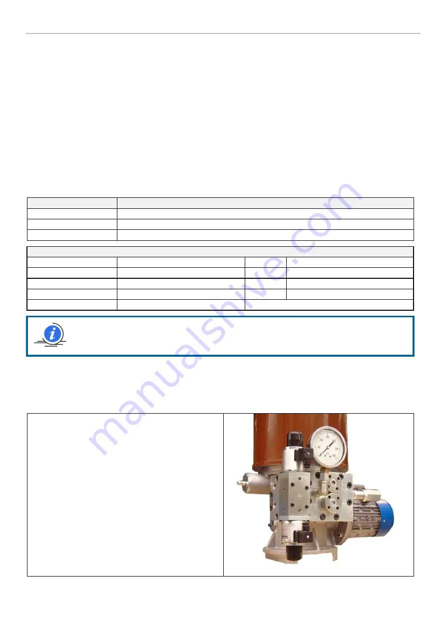
Interchangeable electromagnetic inverter (code 0083420 mounted on standard pump)
The standard pump is prepared for dual line function, with an electromagnetically controlled inverter being assembled as
standard. The inverter can be replaced if it is not working efficiently, without disconnecting the two line pipes (of an
interchangeable type). This is able to reduce maintenance times and the relating installation shutdown.
This version means that the inverter can be replaced without
disconnecting the line pipes. A solution of this type offers the
following advantages:
Ease of assembly and dismantling (only the 4 front Allen
screws need to be loosened and tightened);
Short replacement time;
Minimum installation shutdown time.
GENERAL NOTE FOR ALL INVERTERS
: It is advisable to plan a delay in the de-energizing of the
electromagnets from 2 ÷ 5 sec. to allow complete inversion in relation to the closing time of the pressure
gauge at the end of the line.
Photo 3


