OPERATING
SECTION 4
Page 29
DRESSTA
OM560C99/1E
STARTING AND STOPPING THE ENGINE
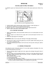
2a. QSK19C engine only. Disconnect the EPS connector of the engine speed sensor. Refer to Fig.
4.21.
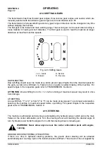
Fig. 4.21. ECM Connector of Engine Speed Sensor
3. Using the ignition switch, crank the engine until the oil pressure monitor light goes out.
4. Reconnect the electrical wire to the fuel pump solenoid valve.
4a. QSK19C engine only. Connect the EPS connector of the engine speed sensor.
5. Start the engine as described under "NORMAL START".
4.12.4. STOPPING THE ENGINE
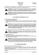
1. Apply the parking brake, lock the transmission direction lever in the neutral position and lower
the bucket.
2. Allow the engine to cool down. Run the engine with no load at idle speed for about 3 to 5
minutes
3. Reduce the engine speed to the idle speed.
ATTENTION:
Failure to do so may result in damage to the engine and turbocharger.
4. Shut down the engine by turning the ignition key to the OFF position. Before leaving the cab
remove the key and lock the cab.
5. Turn off the electrical system master switch and remove the key before leaving the machine
unattended.
4.13. DRIVING THE MACHINE
After starting the engine in temperature above 0
°
C do not start operations immediately. First, carry
out the following operations and checks:
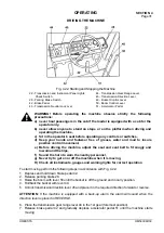
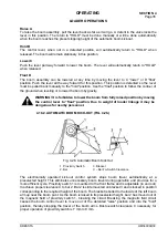
1. Depress accelerator pedal 51 lightly and run the engine at the midrange idle speed for about 3
to 5 minutes.
2. Warm the engine up to the operating temperature. Continue to run the engine with light load until
the engine coolant temperature gauge and torque converter oil temperature gauge pointers
settle in the green area.
Warm-up may be reduced as follows:
a) apply the parking brake,
b) move transmission shift lever to 3
rd
forward,
c) increase the engine speed gradually to maximum speed and run the engine until the pointer
of torque converter temperature gauge is in the upper part of the green area,
Содержание 560C
Страница 1: ...OM560C99 1E OPERATOR S MANUAL 560C SERIAL NUMBERS 15001 AND UP ...
Страница 3: ......
Страница 5: ......
Страница 7: ......
Страница 10: ...SECTION 1 INTRODUCTION ...
Страница 11: ...INTRODUCTION SECTION 1 DRESSTA OM560C99 1E SECTION CONTENTS 1 1 Introduction 3 1 2 Serial Numbers 4 ...
Страница 12: ......
Страница 16: ...SECTION 2 SAFETY PRECAUTIONS ...
Страница 18: ......
Страница 32: ...SECTION 3 MACHINE TRANSPORT AND STORAGE ...
Страница 34: ......
Страница 42: ...SECTION 4 OPERATING ...
Страница 43: ......
Страница 45: ......
Страница 49: ...SECTION 4 OPERATING Page 6 OM560C99 1E DRESSTA UNIVERSAL SYMBOLS FOR INSTRUMENTS AND CONTROLS ...
Страница 88: ...SECTION 5 MAINTENANCE ...
Страница 141: ...SECTION 6 SPECIFICATIONS ...
Страница 143: ......
Страница 151: ...SECTION 6 SPECIFICATIONS Page 10 OM560C99 1E DRESSTA 6 7 WIRING DIAGRAM Fig 6 5 Wiring Diagram ...
Страница 154: ...SPECIFICATIONS SECTION 6 Page 13 DRESSTA OM560C99 1E WIRING DIAGRAM Fig 6 6 Wiring Diagram Of Cab ...


