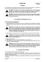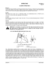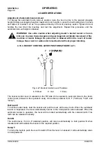
OPERATING
SECTION 4
Page 25
DRESSTA
OM560C99/1E
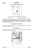
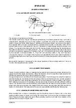
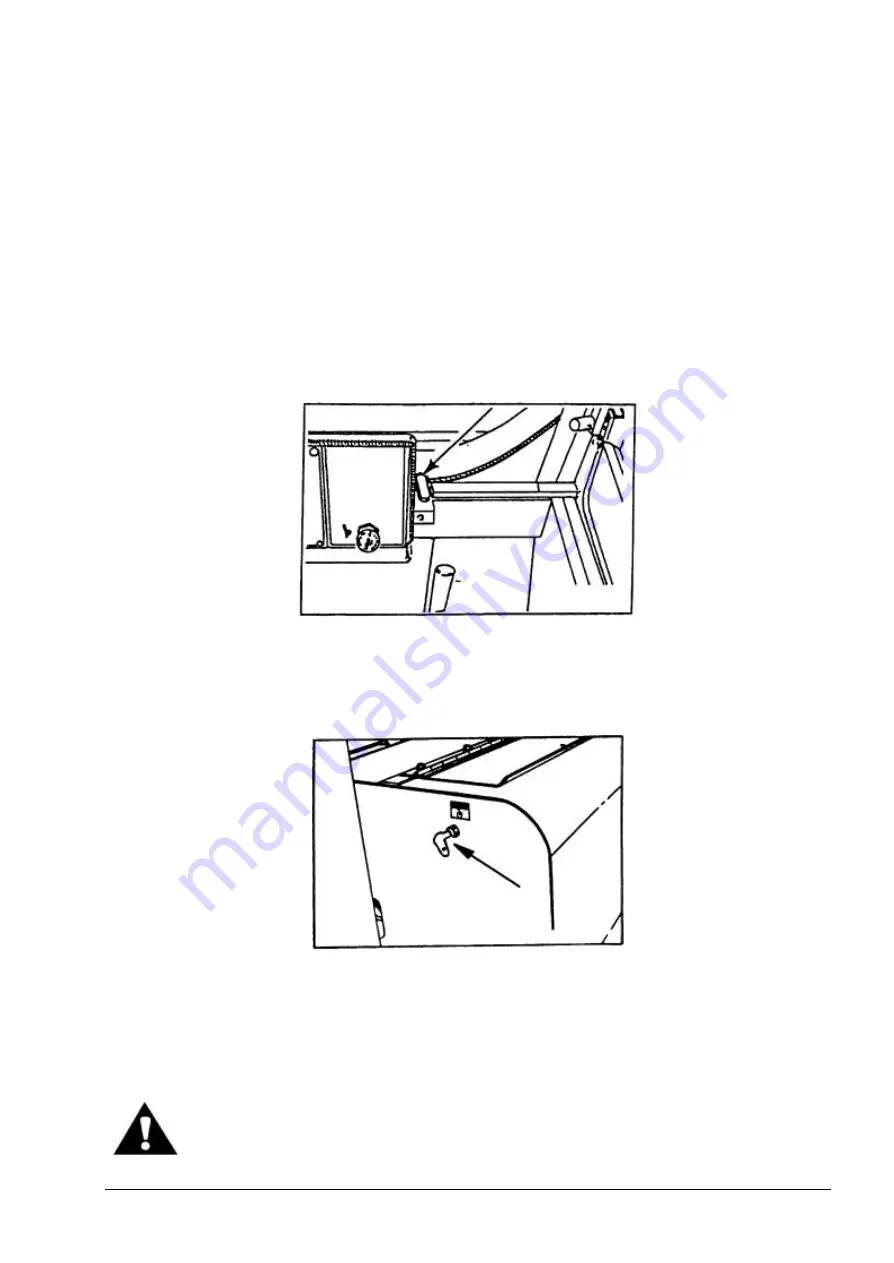
CAB DOOR LATCH
To lock the door depress the arm (with a foot) when the door is in fully open position. The pin 2 will
engage the cutout of arm 1.
The door will be released automatically when moved further to open (until the limiting strip is fully
tightened).
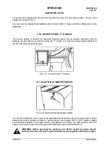
4.10. ACCESS PANEL “T” HANDLE
The access panels to service the hydraulic reservoir filters, the air cleaner elements, and the
batteries are all locked and unlocked using the "T” handle. It is stored in rubber holder attached to
the RH side of the instrument panel.
Fig. 4.17. Access Panel “T” Handle
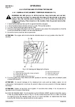
4.11. ELECTRICAL MASTER SWITCH
Fig. 4.18. Electrical System Master Switch
The switch is located on the LH side of the hydraulic tank behind the cab and is connected in series
between the battery positive terminal (+) and receivers, thus turning "ON" or "OFF” battery voltage
to all electrical systems. The master switch must always be turned to the "ON" position when the
engine is running to prevent any damage to the alternator and/or electrical system.
WARNING: Before servicing the machine, turn off the electrical system master
switch and remove the key. Tag the machine to warn against starting the engine.
Содержание 560C
Страница 1: ...OM560C99 1E OPERATOR S MANUAL 560C SERIAL NUMBERS 15001 AND UP ...
Страница 3: ......
Страница 5: ......
Страница 7: ......
Страница 10: ...SECTION 1 INTRODUCTION ...
Страница 11: ...INTRODUCTION SECTION 1 DRESSTA OM560C99 1E SECTION CONTENTS 1 1 Introduction 3 1 2 Serial Numbers 4 ...
Страница 12: ......
Страница 16: ...SECTION 2 SAFETY PRECAUTIONS ...
Страница 18: ......
Страница 32: ...SECTION 3 MACHINE TRANSPORT AND STORAGE ...
Страница 34: ......
Страница 42: ...SECTION 4 OPERATING ...
Страница 43: ......
Страница 45: ......
Страница 49: ...SECTION 4 OPERATING Page 6 OM560C99 1E DRESSTA UNIVERSAL SYMBOLS FOR INSTRUMENTS AND CONTROLS ...
Страница 88: ...SECTION 5 MAINTENANCE ...
Страница 141: ...SECTION 6 SPECIFICATIONS ...
Страница 143: ......
Страница 151: ...SECTION 6 SPECIFICATIONS Page 10 OM560C99 1E DRESSTA 6 7 WIRING DIAGRAM Fig 6 5 Wiring Diagram ...
Страница 154: ...SPECIFICATIONS SECTION 6 Page 13 DRESSTA OM560C99 1E WIRING DIAGRAM Fig 6 6 Wiring Diagram Of Cab ...


