


Instruction No EF 5000 E
01/2004
10
J.
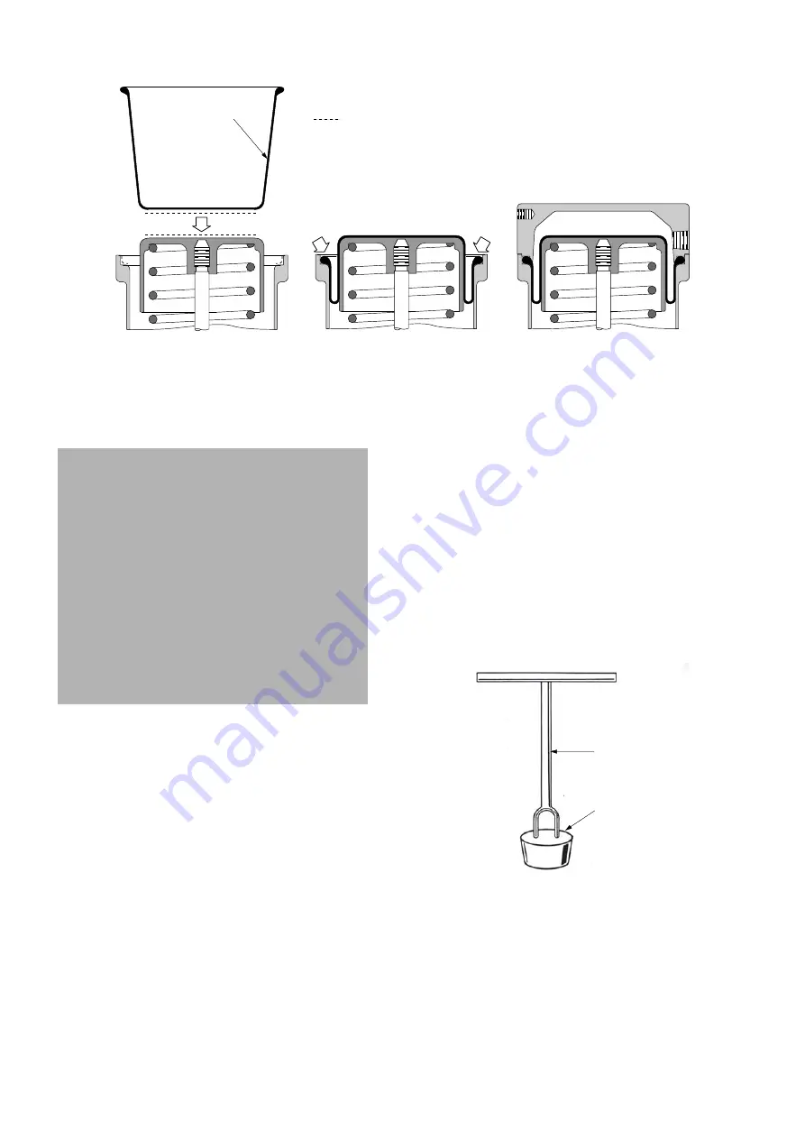
Roll the diaphragm (40) inside the spring barrel
(38) until the bead on the diaphragm is located in
the spring barrel groove (see figure 7, step B).
K.
Place the diaphragm case (42).
L.
Insure that the diaphragm case (42) is evenly
seated on the spring barrel (38), insert the four
capscrews (41) and tighten evenly.
M.
Connect air supply line to diaphragm case (42).
N.
Turn on air supply and check for leaks.
O.
If necessary reposition handwheel (53) and limit
stop (77), (optional) to desired location and place
valve back in service.
9.2
BODY S/A INTERNAL PARTS
During a maintenance of Camflex® II valve it is
necessary to inspect all the internal parts to
determine if they are worm, corroded and damaged,
especially the following seating area:
-
body and seat ring contact area.
-
the sealing surface of the plug and seat ring.
-
the guide surface of the shaft and the guide
bushing.
All parts which are damaged must be replaced by
original Masoneilan spare parts.
9.2.1 Hard Seat Lapping
Lapping is the process of working the valve sealing
parts against each other, with an abrasive, to
produce a close fit. To perform the lapping operation,
proceed as follows.
A.
Clean the seat ring sealing surface in the valve
body and the seat ring shoulder.
B.
Apply a small amount of fine grinding compound
to the seat ring shoulder.
C.
Insert the seat ring into the body and lap lightly
by rotating the seat ring in the body insuring that
the entire seat ring sealing surface in the valve
body is lapped. Do not rotate in one place.
Note: Figure 8 illustrates a simple tool which
may be fabricated to facilitate this lapping
operation on smaller valves.
D.
Remove seat ring and clean thoroughly.
Caution: Insure that the capscrew holes in the
diaphragm case and spring barrel are aligned
to prevent twisting of the diaphragm in
aligning the holes. The diaphragm case (42) is
normally assembled with the air inlet port
placed on the bottom side of the actuator.
Depending on the desired location, It can be
placed in any desired position around the
spring barrel which allows the capscrew
holes to line up. However, the drain hole in
the spring barrel must always be facing down
to allow for draining of any moisture which
may enter the spring barrel cylinder (38). If
the valve is equipped with the optional purge
line that line is inserted into the drain hole.
STEP A
STEP B
STEP C
Outer Face
Glue Limit
Figure 7
FABRICATED
HANDLE
TYPICAL LAB
BOTTLE STOPPER
Figure 8


