

©2017 DreamLine. All Rights Reserved
14
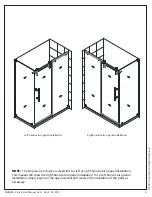
ENIGMA Z Enclosure Manual Ver 1 Rev 4 04/2017
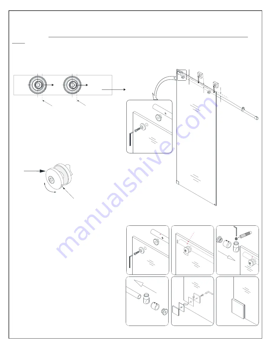
(EQ=Equal distance)
after adjusting the disk, use this hole to hold it
in place with a small allen wrench while
tightening main bolt
Fig. 10
Fig. 9
glass bracket
adjustment
disk
EQ
EQ
measure
Door end of guide rail
High spot of disk bushing
outside
1
4
2
5
3
6
panel side
stopper hole
thread lock
outside
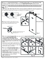
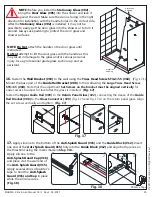
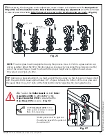
TIP: Mark the location of the high spot on the
outer surface of the adjustment disk with a felt
tip pen to make adjustment easier to see.
*NOTE:
The outer glass bracket disk has an eccentric bushing for adjustment. Be sure to install both
glass bracket disks with the high spot of the bushing pointed toward the door end of the guide rail. See
the detail of the disks below as viewed from inside prior to installing on the glass.
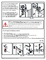
9a.
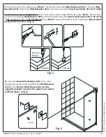
Attach the Upper Guide Rail (#03) to the Stationary Glass (#02) with the Glass Brackets (#07)
and tighten the bolts into the pre-drilled holes in the Upper Guide Rail (#03). Make sure both
adjustment disks are installed in the same direction with the high spot facing towards the door end (see
*NOTE below). Make sure the guide rail is attached parallel with the top edge of the stationary panel
glass. (Fig. 9)
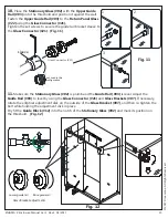
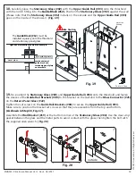
Install the panel-end stopper into the
pre-drilled stopper hole in the Upper Guide
Rail and apply Thread Lock (#20) to the set
screw.
Install the door-end stopper approximately 4”
from the end of the guide rail. (The door-end
stopper position will be adjusted in a later step
after the door glass is installed).
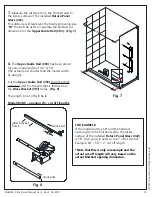
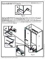
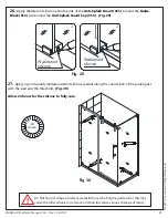
9c.
Slide the Guide Rail Brackets (#08) onto
each end of the Upper Guide Rail (#03) and
secure them. Next, assemble the Wall
Bracket (#19) onto the bottom corner of the
Stationary Glass (#02) with the bolt facing
into the shower as shown in Fig. 10.5.
Use the
supplied gaskets to protect the glass.
(
Fig.
9 and Fig. 10)
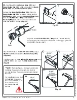
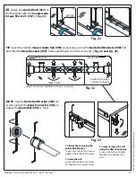
9b.
Slide the Door Stoppers (#01) onto each end of the Upper Guide Rail (#03) and secure them
using the 4mm Hex Wrench (#11).


