

Section 6 -
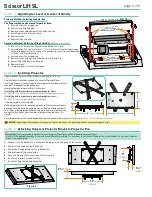
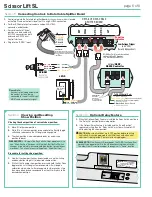
Installing Optional Environmental Air Space Housing
The Environmental Air Space Housing ships in pieces, and must be assembled by the
installer. Height is set by drilling out the knockouts at the desired locations then using
screws to connect side panels.
Draper recommends installing an access panel in the ceiling to allow future access.
The optional Environmental Air Space Housing must be installed to isolate the lift from
the “other space used for environmental air.” Includes trim ring for ceiling opening.
See installation instructions included with Environmental Air Space Housing.
Please Note:
The factory wiring of 'UP' Limit Switch MUST ALWAYS be used
when installed in Environmental Air Space Housing and optional ceiling
closure.
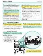
Lower section of
Environmental
Air Space Housing
CEILING TILE
(by others)
TRIM RING
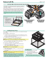
Installing Optional Ceiling Trim Kit
1.
Install Lift.
2.
Install bottom section of
housing in opening by
suspending with wire, or by
mounting directly to the ceiling
joists
(if space permits)
.
3.
Install projector and attach
optional ceiling closure.
For Additional Safety:
1.
Be sure the nuts that attach the threaded
rods to the closure panel are tight.
2.
Wrap a plastic wire tie around the mounting
tab and the threaded rod at all four corners
of the closure panel.
Please Note:
Do NOT use a paper-covered or similar
wire tie — use only plastic wire ties for maximum safety.
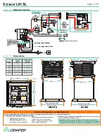
Section 7 -
Installing Ceiling Closure
If unit is equipped with a ceiling closure system, use either as is, or in conjunction with a piece of
existing ceiling tile.
Please refer to diagrams at right for instructions.
1.
If installing with ceiling tile, it may be necessary to cut tile so overall dimensions are same as
(or slightly less than)
closure panel. Place tile into trim frame. Lay closure panel on top
(back side)
of ceiling tile, and tighten screws to hold in place.
2.
If installing large closure, attach brackets to bottom of projector plate.
3.
Attach
5/16
"
(8mm)
threaded rods to slots in projector plate or brackets.
CAUTION:
Ensure nuts and bolts attaching brackets to Lift are completely tightened.
4.
Run unit "up" until bottom pan stops at highest position. Mark position on
5/16
"
(8mm)
rods
flush with ceiling level and cut rods to length
(removing from pan if convenient)
.
5.
Run unit "down" until bottom pan stops at "show" position.
6.
Attach closure to lower end of
5/16
"
(8mm)
rods by slipping into four corner slots
and secure with nuts above and below slots.
7.
Run unit "up" again to highest position. Measure distance by which panel fails
to reach required "closed" height for surrounding ceiling.
CAUTION:
Make sure nuts are completely tightened.
8.
Run unit "down" then re-adjust mounting of
5/16
"
(8mm)
rods in traveling grid to
raise panel required distance.
9.
Test unit operation to confirm that panel will stop in closed position just before
touching ceiling.
CAUTION:
DO NOT hang from, "ride," or pull down on unit. This could create
a failure and cause damage and/or injury.
PLEASE NOTE:
Immediately upon completing surrounding ceiling, operate unit
to confirm that optional ceiling closure panel stops
1/8
"
(3mm)
short of ceiling in
closed position. If closure panel touches ceiling, motor may continue operating
after lift is closed. If it continues to cycle once lift is closed, a failure may occur,
making unit descend rapidly and cause damage and/or injury.
Standard Environmental
Housing Bracket
Arrangement
(B, E, U Sizes)
SL Environmental
Housing Bracket
Arrangement
page 5 of 8
Scissor Lift SL


