background image

3

"

 (100mm)

12"

(304mm)

2

"

(52mm)

7"

(178mm)

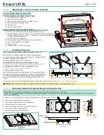
Section 5 -

 Attaching Universal Projector Mount to Projector Pan

Figure 4

Please Note:

 If unit is ordered with optional Universal Projector Mount pre-installed, disregard these instructions. 

If unit is NOT ordered with optional Universal Projector Mount pre-installed, it is necessary to install a new Projector Pan, which includes the Universal Projector 

Mount's rectangular plate.

1. 

Lower unit until the Bottom Pan is resting on a tabletop or other stable and sturdy surface.

2. 

Remove Lifting Cable Bar from Bottom Pan.

3. 

Remove bolts holding Projector Pan to Bottom Pan.

4. 

Remove Projector Pan and set aside.

5. 

Place new Projector Pan with Universal Mount into place.

6. 

Re-attach Projector Pan to Bottom Pan.

7. 

Re-attach Lifting Cable Bar to Bottom Pan.

Preferred Method—Adjusting Projector Pan

The Projector Pan can be moved forward or back.

1. 

Ensure Bottom Pan is supported.

2. 

Remove the Lifting Cable Bar.

3. 

Remove screws holding Projector Pan on Bottom Pan.

4. 

Move Projector Pan forward or back.

5. 

Replace screws.

6. 

Replace Lifting Cable Bar.

Secondary Method—Adjusting Lifting Cable Bar


(if above does not work)

1. 

Run unit to its "Service" position and ensure Bottom Pan is level. 

2. 

Ensure Bottom Pan is not more than ¾" 

(19mm)

 out of level. However, the pan does 

not have to be perfectly level, as long as its positioning is consistent and repeatable 

in "Show" and "Closed" positions.

3. 

Ensure Bottom Pan is supported.

4. 

Remove screws holding Lifting Cable Bar to the Projector Pan.

5. 

Move Lifting Cable Bar forward or back.

6. 

Replace screws.

7. 

Check level again. If still not level, repeat.

Section 3 -

 Adjusting for Level or Center of Gravity

"

(9.5mm) 

-18 x 1"

(25mm) 

hex head 

cap screws for 

attaching Lifting 

Cable Bar to Bottom Pan

BOTTOM PAN

PROJECTOR PAN

LIFTING CABLE BAR

"

(9.5mm) 

-18 x 1"

(25mm) 

hex head 

cap screws for attaching 

Lifting Cable Bar to Bottom Pa

n

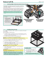
Section 4 -

 Installing Projector

Draper’s optional Universal Projector Mount will hold up to 26 lb 

(12kg)

.

See Installation Instructions included with Universal Projector Mount.
If not using Draper’s Universal Projector Mount, generally the video projector 

should be suspended from the bottom pan  

according to projector manufacturer’s instructions.

If installing with a small closure, maximum projector size is: 


18" x 8¾" 

(45.7 x 22.2 cm)


(width x length x Environmental Air Space Housing height)

.

If installing with a large closure, maximum projector size is:


18" x 18" 

(45.7 x 45.7 cm)


(width x length x housing height)

.

The projector plate is not pre-drilled.
When drilling initial holes for mounting projector, or if for any reason the hole 

placement must be changed, completely lower lift before attempting to drill 

holes. When attaching projector bracket to plate, make sure screws are short 

enough that they do not touch the motor/roller above the plate when lift is 

closed.
Unit and projection system should be operated, checked and adjusted as necessary at this time 

(see Sec. 8 for limit adjustment procedures)

 CAUTION:

 Keep fingers & other objects away from ceiling closure when unit is operating. Serious injury or damage can result.

5

"

(140mm)

2

"

(64mm)

12"

(305mm)

12"

(305mm)

10"

(254mm)

7"

(178mm)

5

"

(140mm)

2

"

(64mm)

12"

(305mm)

12"

(305mm)

10"

(254mm)

7"

(178mm)

5

"

(140mm)

2

"

(64mm

)

12"

(305mm)

12"

(305mm)

10"

(254mm

)

7"

(178mm)

page 4 of 8

Scissor Lift SL

Содержание SL

Страница 1: ...stallation and operation Minimum clearance above ceiling level varies according to height of projector optional projector mounting bracket optional ceiling closure and optional Environmental Housing 3 Arrange to provide service access to the unit 4 When installed with Environmental Air Space Housing unit is suitable for use in an environmental air space in accordance with Section 300 22 C of the N...

Страница 2: ...nstalled in environmental air space housing and optional ceiling closure the ALTERNATE wiring for up limit switch may be used see Alternate Wiring schematic on page 5 36 Custom products installations may not be reflected in this manual Call Draper Inc if you have questions about the installation of custom products or any questions about your installation Caution Before servicing unit disconnect ha...

Страница 3: ...witch operate the lift in the up direction so the lift s control encoder will recognize it s home location Until you do this the Down function will not work You must also do this if the Scissor Lift ever loses or is disconnected from the power When unit is first operated be cautious If unit fails to operate properly press STOP and recheck electrical connections before proceeding Cycle unit down an...

Страница 4: ... or back 6 Replace screws 7 Check level again If still not level repeat Section 3 Adjusting for Level or Center of Gravity 9 5mm 18 x 1 25mm hex head cap screws for attaching Lifting Cable Bar to Bottom Pan BOTTOM PAN PROJECTOR PAN LIFTING CABLE BAR 9 5mm 18 x 1 25mm hex head cap screws for attaching Lifting Cable Bar to Bottom Pan Section 4 Installing Projector Draper s optional Universal Project...

Страница 5: ...iling tile it may be necessary to cut tile so overall dimensions are same as or slightly less than closure panel Place tile into trim frame Lay closure panel on top back side of ceiling tile and tighten screws to hold in place 2 If installing large closure attach brackets to bottom of projector plate 3 Attach 5 16 8mm threaded rods to slots in projector plate or brackets CAUTION Ensure nuts and bo...

Страница 6: ...ow Position requires adjusting then the Delay Switch must be switched to OFF while adjusting the show position CAUTION Be sure all switches are in OFF position before adjusting limit switch Always be prepared to shut lift off manually when new adjustment is being tested Please refer to wiring diagram PLEASE NOTE If the Scissor Lift loses power the DOWN function will not work until you operate the ...

Страница 7: ...urs use set screws on bottom of fabric roller brackets to compensate for shift and level projector plate Section 14 Adjusting Limit Switches Caution The maintenance service factory limit setting must not be adjusted to a lower position than the preset factory limit setting In addition Draper does not recommend setting show position at the maintenance service position PLEASE NOTE Changing the fully...

Страница 8: ...8 243 8cm SL10 14 35 6cm 10 304 8cm SL12 16 46 6cm 12 365 8cm Section 16 Dimensions There are four sizes of closure See separate instructions for details and dims FRONT VIEW SIDE VIEW There are four sizes of closure See separate instructions for details and dims See Table A TOP VIEW 20 527 mm 20 508 mm 24 624 mm 20 524 mm 16 419 mm 22 583 mm 11 mm x 4 See Table A TOP VIEW 20 527 mm 20 508 mm 24 62...

Отзывы: