Position Numbers
(for reference only)
2
Preparation for Use
EPQ DataNode Series User’s Guide
2-3
Connection Guidelines:
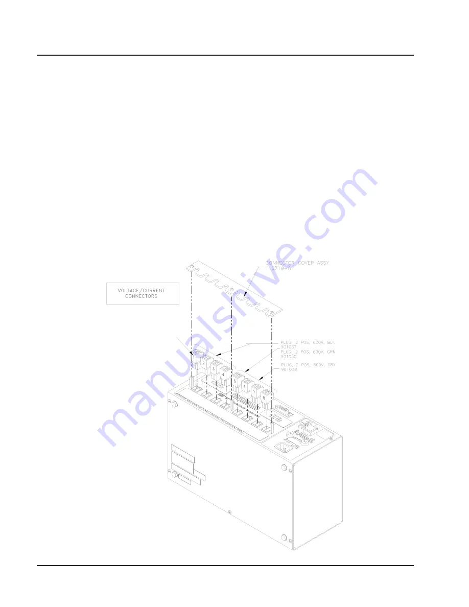
1. Refer to the figure below to connect the Voltage/
Current Plugs with the DataNode.
2. Route power wires in a safe manner in accordance
with good practice and local codes.
3. Make sure all circuits are de-energized before
making connections.
4. Refer to the appropriate connection diagram on
pages 2-4 to 2-11 for wiring configurations.
DataNode 5520: Connecting the Voltage/Current Connectors
5. Connect monitored voltages to the appropriate
Voltage Input connections. Refer to the appropriate
wiring diagram on pages 2-4 to 2-11. Attach phases
A, B, C and Neutral to the instrument if applicable.
(5 - 600 VRMS up to #10 AWG wire)
6. Connect A, B, C and Neutral (if applicable) CT
secondaries to the current input connection. The
5520 is designed to connect to CTs with 5 Amp
nominal secondaries. (.01 - 5 ARMS up to #10
AWG wire)
7. Turn DataNode ON by pushing the power switch.
Proceed to Chapter 3, Operation.


