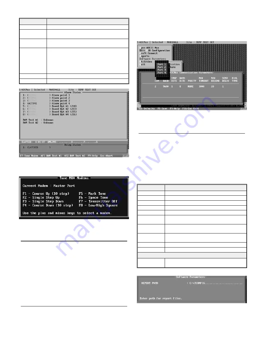
Table D - Craft Connect Functions
Function
Description
INQUIRE
Retrieve and display the unit
*
s configuration status.
DOWNLOAD
Configure the unit using the selected configuration (re-
fer to the title bar). Press <ENTER> to start.
UPLOAD
Retrieve configuration from the unit. Overwrites se-
lected configuration. Press <ENTER> to start.
MONITOR
Monitor operational status. (Fig. 6) Screen shows local
alarm and control point status. (Shown in this screen
only.) It also displays four operational status points, for
use by DPS Technical Support. Press F7 for the Modem
Tuning window.
This function is not fully implemented at this time.
Terminal - PAD Observe data on any port. Select port with function key.
QUIT
Exit this function and return to the Main Menu.
Modem Tuning
If the MUX is equipped with modems on any of the ports, set
the modem levels while in the monitor mode. Press F7 to access
the Modem Tuning Window (Fig. 10). Use the + (plus) and -
(minus) keys to select the port (selected port is displayed in the
first field of the window). With a level meter on the port to be
adjusted, use the keys listed in the window to control the trans-
mit and raise or lower the level, as needed. The receive portion
of the modem has an AGC input, so requires no adjustment.
NOTE: Do not tune above -4dbm or below -34dBm as the
waveforms become distorted at those levels.
Reports
Use this menu item to run configuration reports to the screen,
printer or file. Reports are useful in creating records and refer-
ence files. Such files allow future reference to see how a partic-
ular unit is configured. Several configurations can be reported.
A query box will ask for starting and ending configuration
names (press Tab to see a default box listing of existing config-
urations), report destination and file name (if outputting to file).
Software Parameters
Before a configuration can be downloaded, it is necessary to
set the configuration computer’s com port to match the MUX
craft port parameters. That is done in the Software Parameters
function. See Fig. 11 and Table E.
A sub-menu appears when this function is selected. Select
“Communications” from this sub-menu.Parameters and their
values are given in Table E. Select “Parameters” if you wish to
specify the report directory (Fig. 12).
Table E - Software Parameters Functions
Function
Description
COM
PC Com Port number (1-4).
BAUD
Set only at 9600 Baud.
STOP BITS
Select 1.
DATA BITS
Select 8.
PARITY
Select NONE.
MAX TIMEOUT Time to wait for a response (50-9999 Milliseconds). De-
fault is 3000.
MAX RESEND Number of requests before a timeout will be declared
(0-100). Default is 20.
SEND DELAY
Amount of time before the next request is made. (1-100
seconds). Default is 1.
DIAL TYPE
Not applicable.
QUIT
Exit this function and return to the Main Menu.
Parameters Menu Item
Report Path
Specify the Directory for report files. Normally this is
“Tconfig. See Fig. 12.
4
D-PC-180-10A-XV
March 1997
Fig. 10 - Press F7 while in the Monitor Mode to Access the
Tune Modem Window
Fig. 11 - Configuration Computer Com Port Parameters
must be set before Downloading the MUX
Fig. 9 - Monitor Screen Shows Status of Auxiliary Alarms
and Control Relay
Fig. 12 - Select “Parameters” from the Software Parame-
ters Menu to Define the Directory for Reports


