DPCAV ShutterBug Pro Скачать руководство пользователя страница 3

ShutterBug Pro © 2007-2013

Page 3

Sep-15-2013

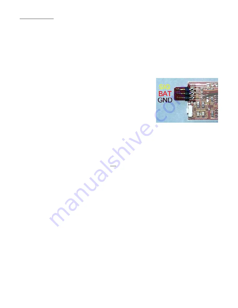
Figure 6, Servo Connector

INSTALLATION
ShutterBug Pro is compatible with R/C servo-activated shutters and direct (hardwired)
connections. The servo method is the most popular because it does not require camera
disassembly or modification.

S

ERVO 

M

ETHOD

As mentioned, a standard R/C servo can be controlled from ShutterBug Pro’s timer
feature or it can be remotely activated using a model R/C system. Servos are available
from R/C model hobby shops. For example, the tiny Hitec HS-55 is low cost and a
popular choice. How you mount it is up to you.

To install the servo on ShutterBug Pro, simply plug it into
the 3-pin connector. The servo cable’s Signal (yellow, or
white) wire is positioned so that it is closest to the outside
edge. The servo is then mounted on the camera with
adhesive or double sided foam tape. The goal is to have
the servo arm press the shutter button, so your
installation should allow that.

D

IRECT 

C

ONNECT 

M

ETHOD

Note: The direct connection method requires delicate electronic soldering, and difficult
modifications to your digital camera that will void the warranty. You, and only you, are
responsible for any damage that may occur in your attempt to modify your camera. Do this
installation at your own risk. Please note that we are unable to offer specific instructions on how
to modify your camera.

The ShutterBug Pro can electronically connect to some digital photo cameras. Its direct
connect interface uses two solid state “switches.” The Stage-1 switch is for focus and
Stage-2 is for shutter (snapshot). The switches are optically isolated, which provides
electrical protection to your camera.

ShutterBug Pro’s direct connection provides the electrical closure to the contacts on your
camera’s shutter button. Stage-1 (focus) is switched-on first, followed by Stage-2
(shutter). All switches are turned off after a short final delay. Total focus/shutter activation
time will depend on the settings you have chosen (please see System Programming
section).

Содержание ShutterBug Pro

Страница 1: ...our grams size 0 9 x 1 2 WHAT IS IT ShutterBug Pro is a convenient accessory for expanding a camera s shutter features It precisely operates the focus and shutter stages upon a timed event or remote control signal It can even auto repeat the shutter for a rapid series of shots It also can be used to prevent a digital camera from turning itself off which is a real lifesaver in some applications A h...

Страница 2: ...e Figure 4 for battery connections PUSH BUTTON SWITCH The onboard pushbutton switch can be manually pressed to snap a photo This is ideal for testing your camera setup It is available in all modes of operation WIRELESS REMOTE CONTROL ShutterBug Pro s 3 wire cable can be plugged into a spare channel of a model R C receiver not included Brands such as JR Futaba Hitec and Airtronics are compatible Yo...

Страница 3: ...r button so your installation should allow that DIRECT CONNECT METHOD Note The direct connection method requires delicate electronic soldering and difficult modifications to your digital camera that will void the warranty You and only you are responsible for any damage that may occur in your attempt to modify your camera Do this installation at your own risk Please note that we are unable to offer...

Страница 4: ... sensitive So they must be wired to match the polarity of your camera This can be determined by using a voltmeter across the camera s shutter button switch contacts during its resting state Direct Connect Method 2 Wire Not all cameras do a focus when the shutter button is depressed Or perhaps you do not want to use the cameras auto focus feature If so only two wires are needed N A Not Used SHUT Sh...

Страница 5: ...You can install ShutterBug using 3 wires too This is usually wired as a common negative ground arrangement However some cameras will need a common positive ground If you aren t sure what to do then use the 4 wire method FOC Focus Positive SHUT Shutter Positive COM Common Negative COM Common Positive FOC Focus Negative SHUT Shutter Negative ...

Страница 6: ...nfigured with the following settings Of course any of these settings can be changed to suit your application CONFIGURATION TYPE DEFAULT VALUE RANGE OF VALUES Wake up Standalone Interval Period 60 2 to 120 Wake up Standalone Interval Units Seconds Sec Sec10X Min Hr Shutter Repeat Interval Four Seconds 1 to 30 seconds Shutter Dwell Time One Second to 10 seconds Shutter Repeat Hold Mode Repeat Once R...

Страница 7: ...u are done with the step just wait three seconds for the Red LED to wink once ShutterBug Pro will then move to the next step If desired programming can be exited by removing power after the Red LED winks which will leave the remaining values unchanged If your entry is illegal the Red LED will rapidly flash for several seconds as a warning You will then be allowed to try again During steps one thro...

Страница 8: ... time to be less than the camera s maximum allowed inactivity duration For example if your camera turns itself off in five minutes then enter four presses and choose Minutes in Step 2 for four minutes If it turns off in 60 seconds then enter five presses and choose 10X Seconds in Step 2 for fifty seconds STANDALONE When in the Standalone mode this is the time delay before the next snapshot If you ...

Страница 9: ...igure to operate in three different ways They are as follows Once Press and release the shutter button once Do not press again until the next external trigger R C or external switch Repeat Cycle the shutter to take rapid sequence of photos Continue repeat until the external trigger is released Hold At the end of the snapshot continue holding the shutter active until the external trigger is release...

Страница 10: ...our R C equipment and try again Step 8 Neutral Home Servo Position Range 1 Store servo position 2 Load factory default 3 Skip no change This entry allows you to precisely set the neutral home servo position Use your R C transmitter or servo signal simulator to position the servo arm away from the camera s shutter button Once it is where you want it enter one press Step 9 Stage 1 Focus Servo Positi...

Страница 11: ... operational mode The blink code is defined as follows One Blink R C Trigger mode Two Blinks Standalone mode Three Blinks External Trigger Switch mode If the R C servo signal becomes corrupt or is no longer detected the Red LED will constantly blink until the R C servo signal is restored Note This applies only to the R C trigger mode During a snapshot the Yellow LED will operate as follows Rapid F...

Страница 12: ...age to other customer owned equipment 5 Any product whose serial number has been altered defaced or removed 6 Batteries cords wall mounted transformers cosmetic parts or routine maintenance 7 Adjustment of customer operated controls and features as explained in the instruction guide WHEN SERVICE IS NEEDED DURING THE WARRANTY PERIOD 1 Contact DPC using the contact us link instructions found at www ...

Страница 13: ...simple low cost design is fine Q I m using the Standalone mode with very long time delays The problem is that my camera turns itself off when it is idle for more than five minutes What can I do A Unlike the R C and External Switch trigger methods the Standalone mode does not have a camera keep awake feature For long duration timed snapshots the servo s Stage 1 position can be used to turn the came...

Страница 14: ......

Страница 15: ...Programming Summary ...

Страница 16: ...well Time 0 skip 1 0 5S 2 1S 3 1 5S 20 10Sec 500mS per press 5 Shutter Repeat Hold Mode 0 Skip 1 Once 2 Repeat 3 Hold 6 Focus Dwell Time 0 Skip 1 Off 2 1S 3 1 5Sec 20 10Sec 500mS per press 7 External Trigger Mode 0 Skip 1 R C Signal 2 External Switch 8 Servo Neutral Home Position 1 Store 2 Default 1 0mS 3 Skip 9 Servo Stage 1 Position 1 Store 2 Load Default 1 5mS 3 Skip 10 Servo Stage 2 Position 1...

Отзывы: