


3 7
1.
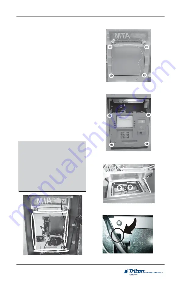
Locate the control panel trim
included with the unit accessories.
On the back side are 4 clips (Figure
1a) that will align with 4 slots on
the sleeve control panel (Figure 1b).
2.
Before mounting the trim, ensure
the speaker wires won’t be pinched
when installing. These will be
connected later. Align the trim clips
with the sleeve slots and insert
until the trim is seated on the control
panel.
3.
Once the trim is in place, open the
cabinet on the back side of the
sleeve and secure the trim panel
with 16 Phillips head screws
included in the accessory kit. (4 on
each side, Figure 2a).
I
NSTALLING
C
ONTROL
P
ANEL
T
RIM
Figure 1a. Location of clips on con-
trol panel fascia.
Figure 1b. Location of slots on sleeve
control panel.
Figure 2a. Location of fascia screws.
Figure 2b. Panel opened and screw
locations.
Figure 2c. Blown-up view of screw lo-
cation.
Note
2 screws holes are located inside the
small silver panel. Recommend sliding
the dispensing mechanism back
approximately one (1) foot and use a
magnetic Phillips driver to hold screws.
Screw holes are located in upper slot
shown in Figures 2b and 2c.
S
ITE
P
REPARATION
/I
NSTALLATION
Содержание Triton FT5000
Страница 8: ...THIS PAGE INTENTIONALLY LEFT BLANK 8 FT5000 SITE PREPARATION AND INSTALLATION GUIDE ...
Страница 9: ...9 ATM INSTALLATION FOR ACCESSIBILITY ...
Страница 21: ...21 ATM ENVIRONMENTAL PRECAUTIONS CHECKLIST ...
Страница 23: ...23 SITE PREPARATION INSTALLATION Ground exterior ...
Страница 44: ...44 FT5000 SITE PREPARATION AND INSTALLATION GUIDE THIS PAGE INTENTIONALLY LEFT BLANK ...
Страница 45: ...45 POWER AND COMMUNICATION ...
Страница 48: ...48 THIS PAGE INTENTIONALLY LEFT BLANK FT5000 SITE PREPARATION AND INSTALLATION GUIDE ...
Страница 49: ...49 NMD 100 DISPENSING MECHANISM REMOVAL INSTALLATION ...
Страница 54: ...54 THIS PAGE INTENTIONALLY LEFT BLANK FT5000 SITE PREPARATION AND INSTALLATION GUIDE ...
Страница 55: ...55 REAR SERVICE PANEL RSP TCP IP and VSAT INSTALLATION CONNECTIVITY ...


