background image

11/21

NT 1401-F00 12.05 Cold front outlet Intercooler TYPHON e

STEP 3

Close all valves and proceed to pressurize the tank and
discharge the cargo.

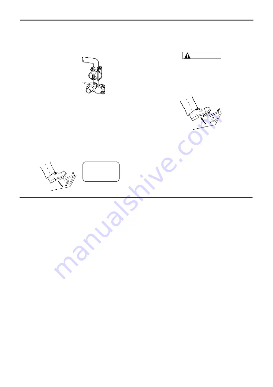
3.5 SHUTTING DOWN PROCEDURE - Vehicle

Mounted

STEP 1

Depress the clutch and disengage the PTO.

STEP 2

Reduce engine speed to idle.

ALWAYS DISENGAGE THE DRIVE BEFORE SLOWING ENGINE
DOWN.

STEP 3

Release the clutch.

NOTICE :

DO NOT attempt to restart the compressor in the follow-
ing instances :

a. If there is still pressure or vacuum in the system. In

this instance, open the vent valve first, than restart the
compressor. Once the pump is up to speed, close the
vent valve slowly.

b. If the compressor input speed is too slow.

CAUTION

PTO

OFF

NOTICE :

THE COMPRESSOR MUST OPERATE AT FIXED SPEED WITHIN
THECOMPRESSOR MODEL SPEEDLIMITS. SPEED MUST
REMAINCONSTANT THROUGHOUT THE OFF LOADING OPE-
RATION.

« FERME »

CLOSE

33..  P

PA

AC

CK

KA

AG

GE

E  O

OP

PE

ER

RA

AT

TIIO

ON

N  ((ccoonnttiinnuueedd))

44..  M

MA

AIIN

NT

TE

EN

NA

AN

NC

CE

E

4.1 Maintenance schedules

After each water cleaning of the truck or compressor

Always run the compressor for 15 minutes to remove
any water that inadvertently gets into the piping. 
DO NOT fog or introduce anti-corrosive liquids into the
compressor to prevent corrosion. Use of liquids in the
compressor will cause failure.

After the first 50 hours of operation

Change compressor oil.

After 300 hours and at least every year

Change compressor oil.

Weekly
1.

The compressor should be run once a week for at

least 15 minutes to prevent moisture from collecting
inside. This will reduce the risk of corrosion damage to
the compressor and other equipment in the piping.

2.

Inspect and clean air filter. Clean the compressor

external surfaces and cooling fins. Inspect DAILY if
operating in dirty or severe environment. Check the
condition of the inlet filter hose for splits and tears.
Replace or repair as necessary.

3.

Inspect compressor, system piping and components.

Clean or repair as necessary.

4.

Check power transmission line (pulley, shaft, torque

limitor...).

Per manufacturer’s recommendations

Lubricate the universal seal.

Monthly
1.

Check the relief valve(s) for wear and proper settings.

Replace or adjust as necessary.

2. 

Check that the check valve works properly, replace as

necessary.

4.2 Compressor oil draining procedure

Compressor maintenance is limited to a periodic oil
change.

For oils recommended, see § 3.1.

Unscrew and remove the oil filter with its seal. Drip-drain
all the oil contained in the casing.

Carefully clean the oil filter with solvent. Blow out all
impurities with a compressed air blast.

After checking that no particles remain in the filter, reins-
tall it making sure that the seal is in good condition.

Fill the compressor. See § 3.2.

Содержание Blackmer TYPHON 1000

Страница 1: ...fective December 2005 Replaces December 2004 OEM PRODUCT existing only in front version INSTALLATION OPERATION MAINTENANCE SAFETY STORAGE Your distributor BLACKMER ZI PLAINE DES ISLES F 89000 AUXERRE Tel 00 800 890 890 89 Fax 33 3 86 49 87 17 e mail contact blackmer mouvex com ...

Страница 2: ...8 5 3 Warranty claims 20 6 STORAGE CONDITIONS 20 7 AFTER SALES RETURN FORM 21 SUMMARY Page NOTE The item numbers that follow the names of the parts correspond to the reference numbers present on the outline drawings REMARKS Blackmer truck screw type compressors package MUST be instal led in systems designed by qualified personnel The installation MUST be in compliance with local standards national...

Страница 3: ...roperly secured Refer to the Compressor Mounting section of this manual In par ticular the installation shall be done in such a way that no rotary part may be touched by the operator in normal operation NOTICE BLACKMER COMPRESSORS ARE NOT DESIGNED FOR HANDLING LIQUID POWDER OR CONDENSATE TO DO SO WILL VOID THE WARRANTY CONTENTS OF THE COMPRESSOR TANK PIPING AND FILTERS COULD BE HAZARDOUS TO HEALTH...

Страница 4: ...Thanks to its technology TYPHON compressor is relia ble and has a long service life TYPHON compressor needs very limited maintenance which reduces vehicle downtime TYPHON version 2C drive speed 2000 rpm was defi ned so as to drive it directly through universal joints from a P T O shaft Our compressors are delivered without oil The use of a compressor with an oil level that is not located bet ween ...

Страница 5: ...ty damage and or serious injuries Align the PTO shaft axis with the package pulley axis or refer to the truck PTO documentation Not following assembly instruction can lead to mechani cal ruptures that may create major property damage and or serious injuries 1 3 3 Maximum discharge pressure The maximum acceptable pressure at discharge is indi cated in the tables below as a function of drive speed a...

Страница 6: ... serious body injuries or property damages 1 4 Outlines drawings The overall dimensions of the different packages are given on the table below TYPHON 1000 IC The above dimensions are given with the shaft axis mounted in the closest position to the chair 3 hole loca tions exist on the chair 1st hole 3rd hole 2nd hole Pulley ratio X Y D 1 1 185 524 231 1 1 12 172 503 257 1 1 25 173 503 287 RIGTH DRI...

Страница 7: ...logging of the filter the air sucked inside the filter shall be free of any exhaust fume residue or road dust In front of the filter an area of a minimum of 200 mm should be left free to allow enough space to change the cartridge 2 3 Check relief Safety valve The compressor packages are protected by a check relief safety valve The check valve prevents any air from returning in the compressor when ...

Страница 8: ... is mandatory to comply with the following instructions The shaft must be dynamically balanced Its length and its inclination must be as small as pos sible see table The package shaft must be horizontal with a parallel tolerance with the P T O shaft of 5 The drive shaft slides perfectly well during rotation The jaws of the universal joints are parallel Coupling flanges show no eccentricity nor war...

Страница 9: ...ure Typical start up time for ambiant temperature of 20 C is 150 s at 2 bar package discharge pressure 2 5 1 Electrical wiring diagram 2 5 2 Connection procedure The supply line used to power the intercooler package must be protected by a 16 Amps fuse on both the 12 V and 24 V supply lines to prevent property damage and body injuries The 3 wires to connect the main power supply to the bat tery are...

Страница 10: ... any counter pressure at discharge At commissioning check that the combinations of rota tion speed and discharge pressure of the compressors are in conformity with those indicated in 1 2 During operation the temperature of the surface of a compressor and nearby parts can be in the region of 200 C The compressor and the parts located nearby are thus susceptible of provoking serious burns and proper...

Страница 11: ...the compressor will cause failure After the first 50 hours of operation Change compressor oil After 300 hours and at least every year Change compressor oil Weekly 1 The compressor should be run once a week for at least 15 minutes to prevent moisture from collecting inside This will reduce the risk of corrosion damage to the compressor and other equipment in the piping 2 Inspect and clean air filte...

Страница 12: ...riodically check that belt tension is sufficient Re ten sion belts as required as shown bellow Belt Drive installation 1 Pulleys I Check the grooves for any chips bruising or scoring II Clean up the shaft if necessary and smear some copper slip on it III Assemble each pulley and tapered bush onto the shafts ensuring the correct pulley size goes onto the correct shaft Push them as far onto the shaf...

Страница 13: ... information 4 5 How to change pulley shaft position For a specific use one intallor may want to use a different position for the pulley axis to optimize drive line position In this case please check That you maintain the proper clearance with any truck or equipement stationary or mobile part That you have available the proper length of belt Use XPB belts only To change the pulley shaft position L...

Страница 14: ... close the valve to the point where the relief valve opens do not allow overpressure to the com pressor Read the pressure value This value is the crack pressure Fully close the valve do not allow overpressure to the compressor Read the pressure value This value is the full flow pressure Open the closing valve fully disengage compressor and stop engine The full flow setting pressure should be compl...

Страница 15: ... paying attention to the position of the roller bearing external plate position when it enters the bushing Install the securing ring maintaining the roller bearing Fill in in excess the lipseals with grease Grease bet ween the two lips of the lipseals Use a soft hammer to install them on each side of the bushing Screw the greasing filling port onto the bushing 15 21 NT 1401 F00 12 05 Cold front ou...

Страница 16: ... liquid on both connections sides thermocontact and thermocontact connector For the fan connector replacement Unplug the connector from the fan side Remove the old connector and contacts Connect the 2 new contacts with appropriated tool Insert contacts the white connector Insert cable into the black protection Spray some oily liquid on both connections sides Fan and relay side Heat the black prote...

Страница 17: ...ulley shaft 1 12 207698 Securing ring 2 13 219591 Joint roller bearing 1 14 200559 Ball bearing 1 15 219594 Securing ring 8 16 204660 Grease filling port 1 17 215580 Screw 4 18 209591 Spacer 4 19 Included in order number 312547 20 Included in order number 312547 21 Included in order number 312547 22 Included in order number 312547 23 220821 Sliding bushing 4 312547 Coupling kit 1 The chair and tra...

Страница 18: ...ux 1 Inclut combiné clapet soupape 8 312538 Echangeur 1 9 312312 avant Chaise 1 10 217037 Rondelle 4 11 205058 Ecrou borgne 4 12 219824 avant Support échangeur 1 13 312542 Kit jauge à huile 1 14 204903 Plaque 1 5 2 TYPHON INTERCOOLER package Exploded view of INTERCOOLER package PART LIST FOR INTERCOOLER PACKAGE INCLUDED IN THE ABOVE EXPLODED VIEW NOTE To order spare parts specify The PART NUMBER a...

Страница 19: ...atériel électrique interne 1 312534 Clapet anti retour 2 3 bar 1 312637 Clapet anti retour 2 0 bar 1 312535 Soupape 1 312523 Ensemble instrumentation 1 Référence Rapport 1 1 Rapport 1 1 12 Rapport 1 1 25 Rapport 1 1 4 Kit poulie courroie 312287 312316 312553 312317 PART LIST FOR INTERCOOLER PACKAGE NOT INCLUDED IN THE PREVIOUS EXPLODED VIEW NOTE To order spare parts specify The PART NUMBER and SER...

Страница 20: ...esence of foreign material inside the compressor body Traces of damage representative of abnormal use of the package Use of non genuine parts Construction of the package not validated by our design office A return sheet shall be filled by the installer or distributor and send to Blackmer in order to claim for a warranty The equipment must be systematically stored in an area shelte red from bad wea...

Страница 21: ...F00 12 05 Cold front outlet Intercooler TYPHON e 7 7 A AF FT TE ER R S SA AL LE ES S R RE ET TU UR RN N F FO OR RM M This Return Form is required to be completed and attached to the equipment for any guarantee claim ...

Отзывы: