79/RT/E7900/770/E-760/660 Series
PK3678_T 04-18 33
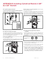
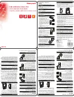
Place 3 spacers (S) on the door (for recent models only).
For concerned lock models, connect all cables (W) to corre-
sponding connectors of the inside trim assembly (E1) when
applicable. Place the inside trim assembly on the door so
that the upper and lower spindles (F) and (G) engage the
thumbturn and the inside lever. Fasten to the outside hous-
ing using the three 1/8" hex head mounting screws (I).
Apply the privacy thumbturn sticker as shown. If in doubt as
to the direction of the arrow, press the auxiliary latch (D5)
to extend the deadbolt, and verify in which direction to ro-
tate the thumbturn to reach the horizontal (privacy) posi-
tion.
RH/RHR LH/LHR
D5
W
F
G
S
T I
Y
I
E2
E1
A.3 Additional steps for ASM Office
Do the following BEFORE placing the inside trim assembly
on the door (page 11, step 5):
Install only parts (M3 and M4) as shown, on the inside trim
assembly.
Install M3 onto M4, then slide both parts onto
the thumbturn.
A.4. Additional steps for ASM/ESM Store room
Do the following BEFORE placing the inside trim assembly
on the door (page 11, step 5):
Put the thumbturn in the vertical position and install only
parts (M2 and M4) as shown, on the inside trim assembly.
The notch on the stopper cam (M2) must engage the tab
on the plate (M4), so that the thumbturn is locked in the
vertical position.
Install M2 onto M4, then slide both parts onto the
thumbturn.
The thumbturn should be locked in the vertical position
APPENDIX A
Mortise Models


