background image

18 

Exit Device Operators 630/750/79E/RT/E7900 Series/ Generation E-730          PK3677_T 

10-18

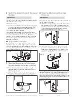
22.  The cap has a small groove on one edge 

(to allow ease of removal) this should be 

facing down. Insert bottom snap of cap 

in handle hole below the cylinder. With a 

small screwdriver, push top snap of cap 

down while pushing the cap into place to 

cover the keyhole (Fig. 15)

23.  To remove the cap, insert a small flat 

screwdriver into this groove and gen-

tly pry the cap off, being careful not to 

damage it. (You may want to cover the 

bottom of the lever to protect the finish 

from being scratched through the process 

of removing the cap). (Fig.16)

CAUTION

WARNING

IMPORTANT

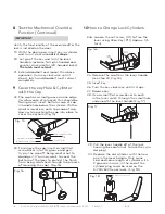
Verify the functionality of the override after the 

lock is installed on the door:
19.  With the door open, insert key in cylinder 

and turn it clockwise until it stops.

20.  Let go of the key and turn the lever 

handle (clockwise for right-handed and 

counter-clockwise for left-handed locks). 

The latch must retract.

21.  Extend deadbolt and repeat the above 

operation (turn key clockwise until it 

stops), latch and deadbolt must retract 

completely.

Fig. 16

Fig. 17

23a.  Loosen the set screw (01) to free the 

lever using Allen Key (P1) (Approx. 1/4 

turn).

24.  Remove the cap from the lever handle 

(see step 23, Fig. 16).

25. Insert key.
26. Turn the key clockwise until it stops. 
27. Release key.
28.  Use a small flat screwdriver to push 

in the lever catch through the small hole 

underneath the lever handle (Fig. 17).

29.  Pull the lever handle off of the lock 

housing (be careful not to lose the cylin-

der plug).

30.  Replace the old cylinder with the new 

one in the lever handle. Only same 

kind and same length of cylinder with 

2 grooves in cross, in the end of the 

cylinder plug could be used on the 

E-730/630 Series locks. (Fig. 18)

Fig. 15

(I)

Hole below cylinder

Bottom snap (First)

Top snap (Second)

Push (Third)

Fig. 18

2 Grooves in cross

Fig. 16A

(P1)

(01)

8   Test the Mechanical Override 

Function (Continued)

10  How to Change Lock Cylinders

9   Cover the key Hole & Cylinder 

with the Cap

Содержание 630 Series

Страница 1: ...E 730 Series 630 Series 750 Series 79E RT E7900 Series Exit Device Operators 630 750 79E RT E7900 Series Generation E 730 Installation instructions PK3677 T 2018 09 EN ...

Страница 2: ... Lock 9 G Operating the Emergency Override 10 H Test the operation of the 630 Lock 11 J Installing the Mechanical Override 12 Parts and Tools List 12 1 Upon unpacking the Lock 13 2 Preparing the Outside Housing for the Installation of the Lever 13 3 Preparing the Lever Handle and Cylinder for Installation 14 4 Steps to attach the Lever Handle to the Lock Housing 14 5 Attaching the Lever Handle to ...

Страница 3: ...closure T 2 X Pan Head Screws 8 32 X 1 2 Tools Required Safety glasses 5 16 7 9mm drill bit 1 2 13mm drill bit 1 25mm drill bit Drill Awl or center punch Hammer Rubber mallet Small flat screwdriver Philips 2 screwdriver Spanner screwdriver No 6 1 8 Allen key Adjustable square Tape measure Pencil Tape Cleaning supplies drop cloth vacuum B A C D E F Q G H G J K E S COVER T S SUPPORT W W S SCREW Mech...

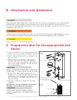
Страница 4: ...ill the holes in the door required for the exit device according to the manufacturer s instructions CAUTION WARNING IMPORTANT Drill from both sides of the door to prevent unsightly damage Refer to template for drill size and depths 3 through holes From the inside counter bore 5 16 dia X 3 4 deep See Drilling Template 2 or 4 Holes Backset Vertical Line Inside of Door 3 4 Fig 1 Fig 2 B Introduction ...

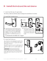
Страница 5: ... it For Mechanical Override Models refer to page 12 Assemble the lever on the outside housing in the horizontal rest position appropriate to the handing of the door as shown Simply push the lever onto the tube until it clicks in place If more force is required to engage the handle use a rubber mallet Test the attachment of the handle by pulling smartly on it For mortise exit devices install the mo...

Страница 6: ...ce mechanism to jam the lock assembly once it is tightened down 4 2 Place the outside housing B on the door with gasket C if required 4 3 Attach Adaptor Plate E to the lock B using 3 Flat Head screw F 12 24nc 4 4 Attach the Exit Device chassis G to the Adaptor Plate E using 2 screws or 4 screws H depend ing on the Exit Device For Detex only use 2 or 4 Flat washers Q 4 5 Make sure the lock and the ...

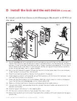
Страница 7: ...gasket C and the hole H3 For the hollow doors the wires shall pass inside the door to come out from the hole H2 5 3 Place the outside housing B on the door with gasket C if required 5 4 Attach adaptor plate E to the lock B using 3 flat head screw F 12 24unc for solid doors make sure that the wires are in the slot S1 5 5 Attach the Exit Device chassis G to the Adaptor Plate E using 2 screws or 4 sc...

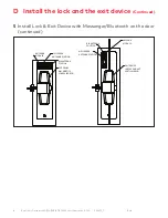
Страница 8: ...MOUNT VERTICALE ROD ANTENNA MODULE MESSENGER ANTENNA POSITION BLE ANTENNA POSITION ANTENNA MODULE EXIT DEVICE RIM MORTISE CONCEALED ROD MESSENGER ANTENNA POSITION BLE ANTENNA POSITION 5 Install Lock Exit Device with Messenger Bluetooth on the door continued D Install the lock and the exit device Continued ...

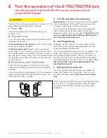
Страница 9: ... For RT lock series please refer to system 6000 manual A Test the Lock Before Programming Normal Entry Use the Test keycard with the reader The red and green LEDs each flash once and then the green LED flashes for four seconds Turn the outside lever downward while the green LED is flashing The latch or rod retracts fully Release the lever then turn it again The latch or rod must not retract after ...

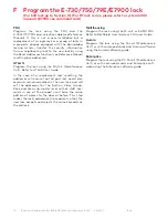
Страница 10: ...ds remain cancelled in the new lock and will set the addresses for the Section Floor Group Zone and Area sub master level so that staff key cards in use at the property will have the same pattern of access to the door as before This step makes the lock replacement transparent so that the new lock accepts and rejects the same keycards as the old lock Multihousing Program the lock using the M unit o...

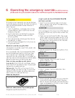
Страница 11: ...k the lock audit records the FDU number the Authorization key card number the date and the time Hardware Required Front Desk Unit FDU and Communication Cable Minimum Authorization Keycard Required Programming Authorization PA G Operating the emergency overrideFor RT lock series please refer to system 6000 manual For multihousing refer to RezShield manual Steps to activate the E 730 630 750 79E ele...

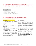
Страница 12: ...ight hard to turn or does not return easily to its horizontal rest position check the spindle length vs the door thickness the spindle may be too long Check that the slotted end of the spindle is inserted in the lock housing hub not the exit device 3 Electronic A Programming Program the lock with at least one user using the Oracode Maintenance Unit Generate a valid code for this user Recommendatio...

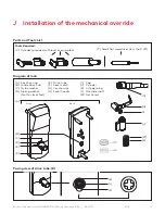
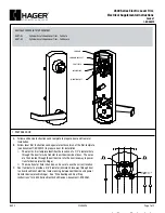
Страница 13: ...el E Drive tube F Lever catch G Countersink H Lever handle I Cap J Cylinder K Cylinder plug L Override shaft K1 Set Screw Back A H E B D F I J K K1 E L F G C Front J Installation of the mechanical override Parts and Tools List Facing view of drive tube E Diagram of lock Tools Required U Cylinder provided with lock or equivalent T Small flat scewdriver less that 1 8 ...

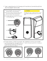
Страница 14: ... WARNING IMPORTANT Assemble the lever cylinder and lock compo nents before affixing the entire unit to the door A The small indents on the cross of the override shaft in line horizontally B The nylon washer and the spring washer not for lever feel on the drive tube C The lever catch in the out position D Cylinder and 2 keys for 630 K C included in the hardware bag 1 Upon unpacking the lock housing...

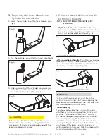
Страница 15: ...er plug does not fall out insert the key into the cylinder The key will be horizontal See Fig 5 3 Preparing the Lever Handle and Cylinder for Installation 3 Insert the cylinder into the lever handle see Fig 3 4 Steps to attach the lever handle to the lock housing NOTE THE POSITION OF THE KEY IS VERY IMPORTANT CAUTION WARNING IMPORTANT The key and the countersink must be in the positions shown in F...

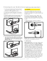
Страница 16: ...ever handle with a cloth or other material to protect the finish of the metal 9 Remove the key The lock will look as shown in Fig 10 Gently check the rotation of the lever handle It should easily rotate approximately 45º Troubleshooting Right handed Lock Turn the lever handle clock wise without forcing it If it stops at approxi mately 15º it was not assembled correctly as shown in step 4 Fig 6 7 D...

Страница 17: ...steps 2 3 4 5 and make sure that the lever looks like Fig 10 and repeat this verification process Step 6 Fig 11 CAUTION WARNING IMPORTANT This test can only be performed when the lock is not affixed to the door 16 Without using the key turn the lever han dle clockwise for Right handed locks or counter clockwise for Left handed locks The inside drive hub should not rotate when the handle turns Fig ...

Страница 18: ... and counter clockwise for left handed locks The latch must retract 21 Extend deadbolt and repeat the above operation turn key clockwise until it stops latch and deadbolt must retract completely Fig 16 Fig 17 23a Loosen the set screw 01 to free the lever using Allen Key P1 Approx 1 4 turn 24 Remove the cap from the lever handle see step 23 Fig 16 25 Insert key 26 Turn the key clockwise until it st...

Страница 19: ...lever Remove control key F 7 Insert the change key into the remov able core Follow the rest of instructions from step 3 5 of page 12 7 Pins Thinner Adapter 6 Pins Thicker Adapter 10 How to Change Lock Cylinders continued CAUTION WARNING IMPORTANT The Key Override itself does not retract the latch or deadbolt Do not use too much force when turning the key as this may damage the unit To retract the ...

Страница 20: ...e the receiving antenna Increase the separation between the equip ment and receiver Consult the dealer or an experienced radio TV technician for help Statement according to FCC part 15 21 Modifications not expressly approved by dor makaba could void the user s authority to operate the equipment Statement according to FCC part 15 19 This device complies with part 15 of the FCC rules and Industry Ca...

Страница 21: ...Exit Device Operators 630 750 79E RT E7900 Series Generation E 730 PK3677_T 10 18 21 ...

Страница 22: ...omer Services Support Ilco 1 877 468 3555 1 514 340 9025 Saflok 1 800 999 6213 1 248 837 3700 General Information dormakaba us Online Consumable Orders www ilcostore com www saflokstore com To access all of our easy steps please visit our Support Website www kabalodgingsupport com ...

Отзывы: