OPERATING INSTRUCTIONS
26
12/150_23136591
−
C en
STARTING THE MACHINE
WARNING: Under no circumstances should volatile
liquids such as Ether be used for starting this
machine.
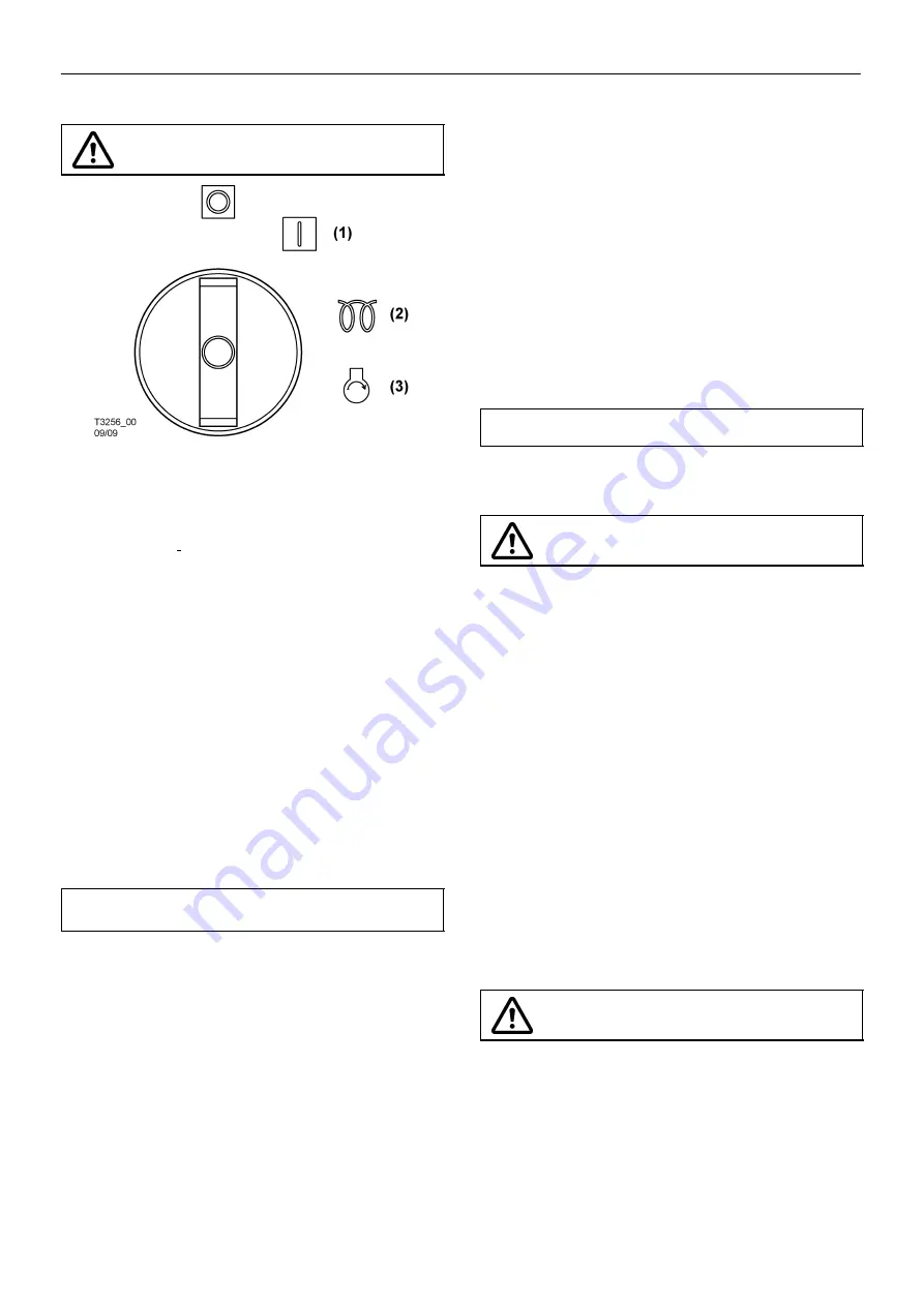
All normal starting functions are incorporated in the key operated
switch.
Turn the key switch to position (1).
The engine fault and
compressor fault lamps will flash.
Wait To Start Lamp.
Turn the key switch to position (1)
until the Wait To Start Lamp
extinguishes.
Turn the key switch to crank position (3) (engine start position).
NOTE: Position (2) not used on AWIR models.
Release to position (1) when engine starts. The engine will now
be running at a reduced speed.
At temperatures below 0
C or if there is difficulty starting first time:
Open the service valve fully, with no hose connected.
Complete starting sequence above.
Close service valve as soon as engine runs freely.
Do not allow machine to run for long periods with service valve
open.
Allow the engine to reach operating temperature.
At this point in the operation of the machine it is safe to apply full
load to the engine.
NOTE:
Wear hearing protection at all times when the engine is started
with the service valve open and air is flowing from the valve.
PUSH AFTER WARM UP
NOTE:
In order to allow the machine to start at a reduced load, a
valve, which is operated by a button located on the instrument panel,
is incorporated in the regulation system. (The valve automatically
returns to the start position when the machine is switched off and air
pressure relieved from the system).
Allow the engine to reach its operating temperature
−
then press the
button (7)
.
At this point in the operation of the machine it is safe to apply
full
load
to the engine.
DUAL PRESSURE WHEN FITTED
Machines which operate in excess of 7 bar (100 psi) can optionally
be fitted with a dual pressure switch inside the unit. This switch
selects between 7 bar (100 psi) and the machine rated pressure,
cfm remains nominally constant.
Starting and stopping are unaffected by the selection and during
normal running the selector switch may be safely operated.
Precaution must be taken to ensure that downstream equipment is
rated to suit the available pressure.
The pressure gauge indicates which setting has been selected.
STOPPING THE MACHINE
Close the service valve.
Allow the machine to run unloaded for a short period of time to
reduce the engine temperature.
Turn the start switch to the
0
(off) position.
NOTE:
As soon as the engine stops, the automatic blowdown valve
will relieve all pressure from the system.
If the automatic blowdown valve fails to operate, then pressure must
be relieved from the system by means of the service valve(s).
CAUTION:
Never allow the machine to stand idle with
pressure in the system.
EMERGENCY STOPPING
In the event that the unit has to be stopped in an emergency,
PUSH
ONE OF TWO RED SAFETY SWITCHES ON SIDES OF THE
MACHINE, OR TURN
THE KEY SWITCH LOCATED ON THE
INSTRUMENT PANEL TO THE
0
(OFF) POSITION.
RE
−
STARTING AFTER AN EMERGENCY
If the machine has been switched off because of a machine
malfunction, then identify and correct the fault before attempting to
re
−
start. If one of the side switches has been used to stop the
machine, turn the switch to the ”on” position before re
−
starting.
If the machine has been switched off for reasons of safety, then ensure
that the machine can be operated safely before re
−
starting.
Refer to the
PRIOR TO STARTING
and
STARTING
THE UNIT
instructions earlier in this section before re
−
starting the machine.
MONITORING DURING OPERATION
Should any of the safety shut-down conditions occur, the unit will
stop.
Refer to the Wedge diagnostic display codes table for a listing of
shutdown conditions.
CAUTION:
To ensure an adequate flow of oil to the
compressor at low temperature, never allow the
discharge pressure to fall below 3,5 bar
(50 psi)
Содержание 12/150
Страница 42: ...MACHINE SYSTEMS 40 12 150_23136591 C en ...
Страница 44: ...MACHINE SYSTEMS 42 12 150_23136591 C en WIRING DIAGRAM 23296643_B SHEET 2 ...
Страница 46: ...MACHINE SYSTEMS 44 12 150_23136591 C en WIRING DIAGRAM 23296643_B SHEET 3 ...
Страница 81: ......
Страница 82: ......

