background image

ENGLISH

7

1

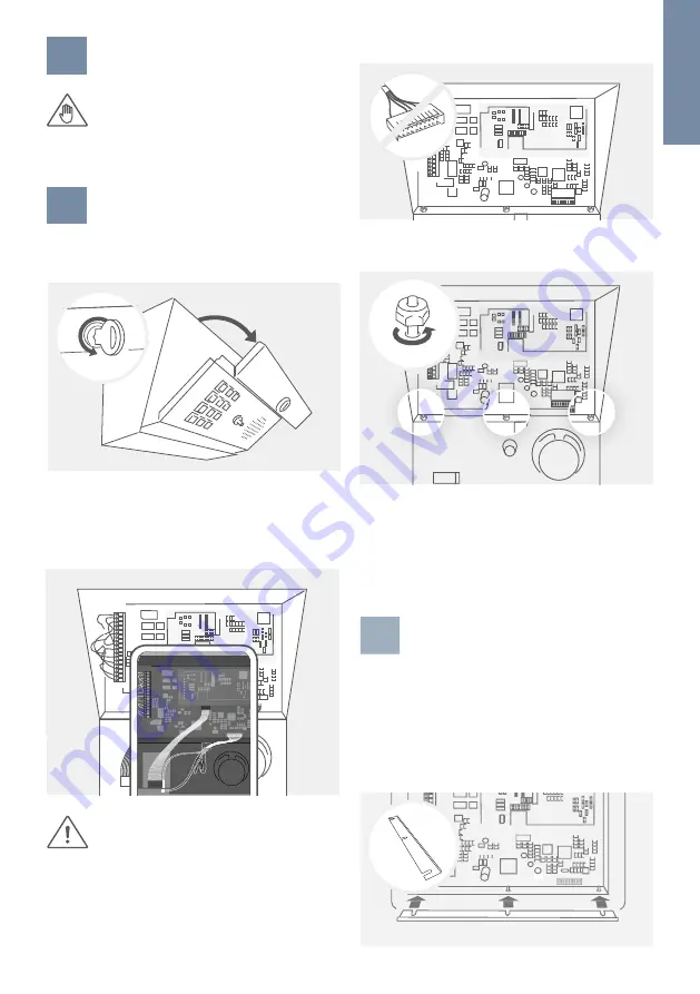
SWITCHING OFF POWER

Switch off the power to all wires leading to 

the assembly location, i.e. the DoorKing

®

 1812, 

telephony line, door chime, electric gate or 

door opener, power supply unit for the 

Doorbird D1812 IP Video door station etc.

2

DISMANTLING THE EXISTING FRONT 
PANEL

Unlock and open the DoorKing

® 

1812 housing with 

the original key. 

Write down (or take a photo) what pins are currently 

used to wire your gate(s) / door opener(s) to pin #11 

to #16 of the main terminal connector (18 pin jack) 

on the DoorKing

® 

1812 control board on the top left 

(relays control).

The DoorKing

® 

1812 control board contains 

static sensitive components. Discharge any 

static electricity from your hands by touching 

a proper ground device before touching the 

control board.

Then unplug all cables between the DoorKing

® 

1812 

control board and the DoorKing

® 

1812 front panel.

Next remove the three nuts fixing the DoorKing

® 

1812 

front panel to the DoorKing

® 

1812 housing.

3

PREPARATION FOR THE FRONT 
PANEL (FLUSH MOUNT ONLY)

APPLIES TO “DoorKing

® 

1812 Plus Flush Mount” ONLY: 

If you plan to assemble the DoorBird D1812 front 

panel to a DoorKing

® 

1812 Plus Flush Mount backbox, 

put the metal bar provided on the three bolts of the 

DoorKing

® 

1812 Plus Flush Mount backbox as shown 

on the sketch below. Fix the metal bar using the three 

nuts and washers you removed previously.  

1

2

3

4

5

6

7

8

9

10

11

12

13

14

15

16

17

18

1

2

3

4

5

6

7

8

9

10

11

12

13

14

15

16

17

18

1

2

3

4

5

6

7

8

9

10

11

12

13

14

15

16

17

18

1

2

3

4

5

6

7

8

9

10

11

12

13

14

15

16

17

18

1

2

3

4

5

6

7

8

9

10

11

12

13

14

15

16

17

18

1

2

3

4

5

6

7

8

9

10

11

12

13

14

15

16

17

18

1

2

3

4

5

6

7

8

9

10

11

12

13

14

15

16

17

18

Keep the three nuts and washers. Store the DoorKing

® 

1812 front panel at a safe place. You may need its 

keypad if you want to e.g. change the DoorKing

® 

1812 

analog telephone settings at a later time (the DoorBird 

D1812 keypad PIN codes, RFID transponders etc. can 

be programmed remotely through the DoorBird App).

Содержание D1812 Series

Страница 1: ...1 Page 2 18 Installation Manual IP Video Door Station D1812 Series VERSION 1 1 MIN HW 1 1 D1812 ...

Страница 2: ...t to function correctly Note Indicates useful information which helps in getting the most out of the product Hazard information Mounting installation and servicing work on electrical devices may only be performed by a qualified eletrician Failure to observe this regulation could result in the risk of serious damage to health or fatal injury due to electric shocks Devices with 110 240 V connection ...

Страница 3: ...nt that varies in temperature Places subject to dust oil chemicals hydrogen sulfide hot spring Places subject to moisture and humidity extremes such as bathrooms cellars greenhouses etc WARNING Places where the temperature is very low such as inside a refrigerated area or in front of an air conditioner Places subject to steam or smoke e g near heating or cooking surfaces Where noise generating dev...

Страница 4: ...l portion of its picture elements always lit or not lit at all This is not considered a device malfunction On devices with intercom due to the environmental sound around the device it may hinder smooth communication but this is not a malfunction On devices with Username Password the Username Password to access the device is the customer s responsibility Make sure to use a password that cannot be e...

Страница 5: ...daptors Small parts 1x WIFI antenna with extension cable for external mounting 1x Screw connection terminal plugs with cables 1x Quickstart guide with Digital Passport 1x Installation manual 1x Main Electrical Unit with call button and front panel The sketches in this manual may differ from the purchased model COMPONENTS ...

Страница 6: ... and WiFi access points or WiFi Back 11 Main Electrical Unit 12 Screw connection terminal 13 Diagnostic LED Lights up a few seconds after connecting the device to power 14 Clips to mount optional DoorBird 2 Wire Ethernet PoE Converter A1071 or DoorBird AC DC Converter A8004 15 Thread to connect WiFi antenna DEVICE Front 4 5 6 7 9 10 1 2 3 1 Microphone 2 Light Sensor For night vision mode 3 Keypad ...

Страница 7: ...ixing the DoorKing 1812 front panel to the DoorKing 1812 housing 3 PREPARATION FOR THE FRONT PANEL FLUSH MOUNT ONLY APPLIES TO DoorKing 1812 Plus Flush Mount ONLY If you plan to assemble the DoorBird D1812 front panel to a DoorKing 1812 Plus Flush Mount backbox put the metal bar provided on the three bolts of the DoorKing 1812 Plus Flush Mount backbox as shown on the sketch below Fix the metal bar...

Страница 8: ...k cable which is plugged into a network switch router with Internet access from the inside of your building to the assembly location The network cable between the assembly location and the network switch router can have a maximum length of 80 m 262 ft IEEE 802 3 If you must span a distance of more than 80 meters 262 feet you can put a network switch in between If you have only two wires available ...

Страница 9: ... Power over Ethernet To power the device via a PoE Switch e g D Link DGS 1008P or PoE Injector e g DoorBird Gigabit PoE Injector A1091 use a CAT 5 cable or higher in accordance with the PoE standard IEEE 802 3af Mode A A CAT 5 cable or higher must be used for this purpose as network signals can only be transmitted over completely insulated shielded and twisted cables If you use PoE as a source of ...

Страница 10: ...nnect them to each other The DoorBird D1812 provides four different cables for this where two are DoorKing 1812 revision independent and two are revision dependent 1 2 3 4 5 6 7 8 9 10 11 12 13 14 15 16 17 18 1 2 3 4 5 6 7 8 9 10 11 12 13 14 15 16 17 18 6 1 RELAYS At first you must connect your gate s door opener s to the DoorBird D1812 Main Electrical Unit by using the same order as you have remo...

Страница 11: ...AND R1 R1 R1 R2 R2 R2 12 15VDC DK PHOUT DK Call Button SPK MIC DK REL MONITORING N O C N C N O C N C PWR LED 6 2 PHONE LINE RELAY MONITORING Connect the cable Phone line cable Part D1812G and the cable Relay monitoring cable Part D1812J from the DoorBird D1812 Main Electrical unit to the main terminal connector 18 pin jack of the DoorKing 1812 control board 1 2 3 4 5 6 7 8 9 10 11 12 13 14 15 16 1...

Страница 12: ...nuing with the installation 1970 010 1871 010 6 4 OTHER CABLES It is possible to connect all other cables and wires to the device conveniently and safely via the labeled screw connection terminals You can connect all necessary cables and wires to the device now Use the cable Interface cable type A Part D1812H for revision 1871 010 and connect it to the white 8 pin jack on the bottom right of the D...

Страница 13: ...pin jack on the top left of the DoorKing 1812 control board see 6 2 phone line and relay monitoring DK CALL BUTTON SPK MIC Depending on the revision number of the DoorKing plug in the cable Interface cable type A Part D1812H or Interface cable type B Part D1812I and connect it to the 8 pin jack on the bottom right of the DoorKing 1812 control board see 6 3 Interface cable You can see the DoorKing ...

Страница 14: ...12 15 V DC 1 A 15W positive pole Please connect the red wire of the power supply unit mains adaptor supplied with the device here if you do not power the device using PoE NOTICE Do not power the device simultaneously via the power supply from the power supply unit mains adaptor and the power supply via PoE LAN PoE RJ45 jack to connect a standard Network cable Cat 5 or higher coming from the Intern...

Страница 15: ... minutes 9 DOWNLOADING AND INSTALLING THE APP Download the DoorBird App by Bird Home Automation onto your mobile device from the Apple App Store or Google Play Store You can always find the most up to date version of the App manual on www doorbird com support If you use WiFi for connecting the device to your Internet Router first go to the DoorBird App WiFi Setup and follow the instructions If you...

Страница 16: ...or areas they are exposed to adverse weather conditions and aggressive substances especially close to frequently used roads in coastal and industrial areas Therefore please consider the following care instructions Unfortunately we cannot accept any liability for damage if these instructions are not being observed Aggressive dirt such as bird droppings should be removed as quickly as possible NOTIC...

Страница 17: ... power supply is able to deliver enough power over the full cable length The device does not connect to network via network cable No Network diagnosis sound In most cases removing the cable and wires from the screw connection terminal plug and reconnecting them to the screw connection terminal plug helps loose contact If the problem still exists please check if the network cable is properly connec...

Страница 18: ...a visitor history and motion sensor You can activate deactivate this function if required If necessary indicate the presence of the device in a suitable place and in a suitable form Please observe any relevant country specific statutory regulations concerning the use of surveillance components and surveillance cameras applicable at the installation site Check with the property owner and your house...

Страница 19: ......

Страница 20: ...www doorbird com ...

Отзывы: