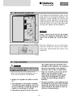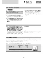
9
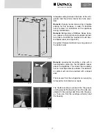
Fig. E14
Fig. E15
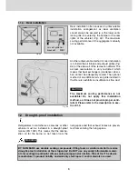
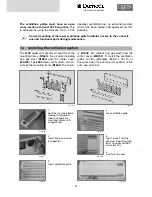
The ventilation grilles must have an open
cross-section of at least 30.78 sq inches.
This
is achieved by using the Dometic L100 / L 200
absorber ventilation and air extraction system
which has been tested and approved for this
purpose.
Fig. E20
Fig. E16
Fig. E17
Fig. E18
Fig. E19
Fig. E21
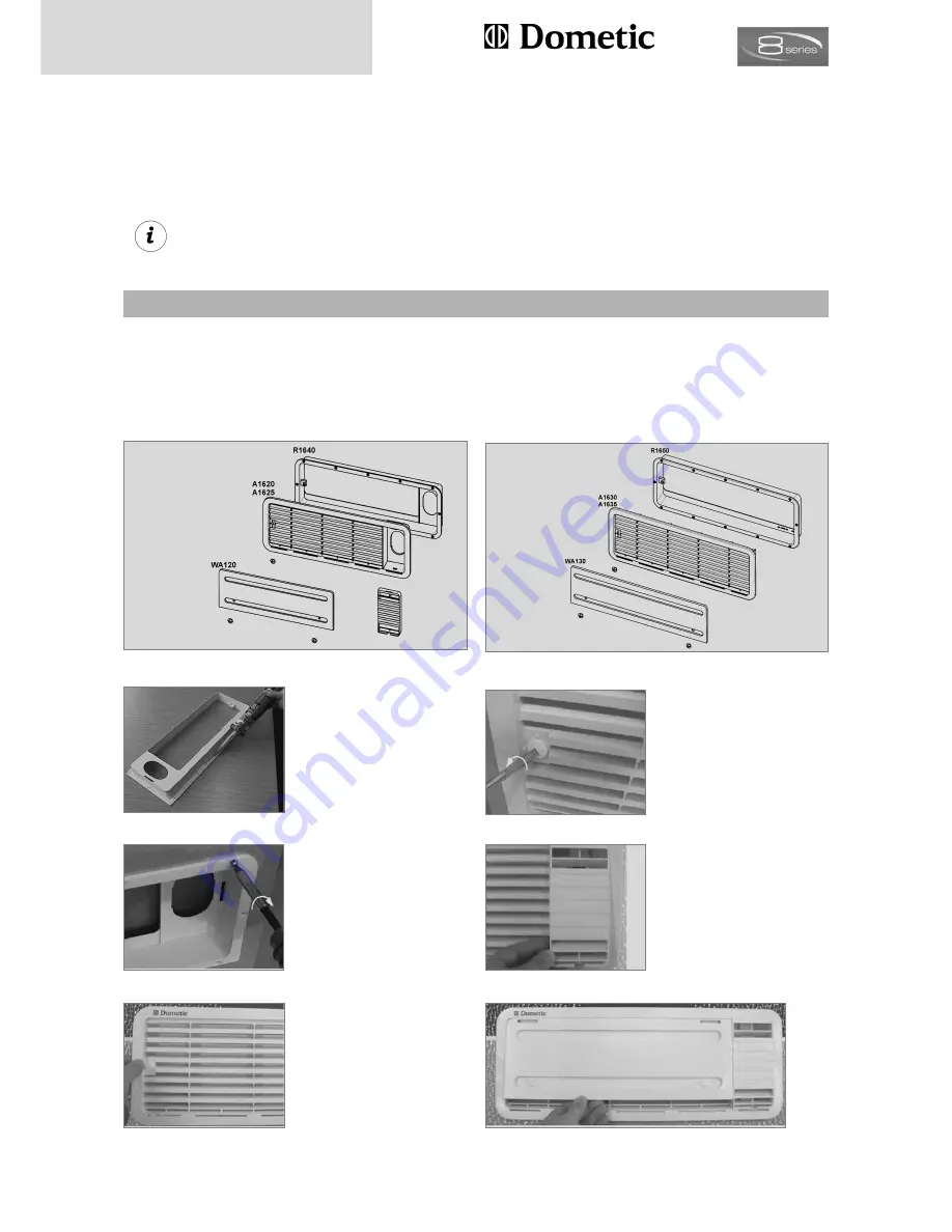
Seal the mounting frame
making it waterproof
(does not apply for
mounting frames with
integral seal).
1.
Insert frame and screw
into position.
2.
Insert ventilation grille.
3.
Lock ventilation grille.
4.
Clip the insert for flue
gas duct in position
(only
for L100 upper ventilati-
on system kit).
5.
Insert winter cover.
6.
THE SIGN OF COMFORT
The
L100
upper vent system kit consists of the
mounting frame (
R1640
), the air grille including
flue gas duct (
A1620
) and the winter cover
(
WA120
). The
L200
lower vent system kit con-
sists of the mounting frame (
R1650
), the air gril-
le (
A1630
, but without flue gas duct) and the
winter cover (
WA130
).
To install the ventilation
grilles, cut two rectangles (
69.09
"
x
24.18
"
) in
the outer wall of the vehicle (for position of the
cuts, see point 6.3).
Correct mounting of the lower ventilation grille facilitates access to the connecti-
ons and functional parts during maintenance.
1.4
Installing the ventilation system
Содержание RML 8551
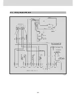
Страница 18: ...18 Fig E35 2 0 Tables and wiring diagrams 2 1 Wiring diagrams 2 1 1 Wiring diagram RM 8xx0...
Страница 19: ...19 Fig E36 2 1 2 Wiring diagram RM 8xx1 THE SIGN OF COMFORT...
Страница 20: ...20 Fig E37 2 1 3 Wiring diagram RM 8xx5...
Страница 21: ...21 Fig E38 2 1 4 Wiring diagram RM 8xx5 with electrical doorlock optional THE SIGN OF COMFORT...
Страница 23: ...23 THE SIGN OF COMFORT...
Страница 24: ......
Страница 47: ...23 THE SIGN OF COMFORT...
Страница 48: ......

