background image

4

1.0 Installation instructions

On installation of the appliance, the technical
and administrative regulations of the country in
which the vehicle will first be used must be

adhered to. Otherwise the refrigerator must be
installed as described in these instructions. 

This appliance is designed for storage of food
and storage of frozen food and making ice. The
refrigerators outlined herein have been design
certified by A.G.A. under ANSI Z21.19
Refrigerator Standard for installation in a mobile
home or recreational vehicle and are approved
by the Canadian Gas Association. The certifica-
tions are, however, contingent on the installation
being made in accordance with the following
instructions as applicable.

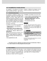
In the 

U.S.A

., the installation must conform with:

National Fuel Gas Code ANSI Z223.1 - 
(latest edition)

Manufactured Home Construction and 
Safety Standard, Title 24 CFR, Part 3280

Recreational Vehicles ANSI A119.2 -

(latest edition)

The unit must be electrically grounded in accor-
dance with the National Electric Code ANSI /
NFPA 70 - (latest edition) when installed if an
external alternating current electrical source is
utilized.

Any applicable local code.

1.1

General instructions

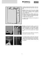
If the appliance is installed on the same side of
the vehicle as the entrance door, it is desirable
that the door does not cover the refrigerator's
vents. (Fig. E1, Clearance door/ventilation grille
at least 1

"

). Otherwise ventilation could be

impaired which causes a loss in cooling perfor-

mance. Awnings are often placed at the door
side of a caravan. This complicates evacuation
of combustion gases and heat through the ven-
tilation grilles (loss in cooling performance)!

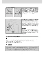
1.1.1 Side installation

Deviations from these installation instructions without prior notification of Dometic
result in Dometic's warranty obligations becoming void!

In 

Canada

., the installation must conform with:

Current CGA B 149 Gas Installation Codes

Current CSA Standard Z 240.4 GAS-
EQUIPPED RECREATIONAL VEHICLES 
AND MOBILE-HOUSING

Any applicable local code

The unit and the exhaust duct system must be in
principle installed so that it is accessible for
maintenance work, can be easily installed and
dismantled and removed from the vehicle wit-
hout great effort.

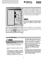
The appliance may only be installed by 
authorised personnel.

The appliance shall be installed in such a
way that it is shielded from excessive heat
radiation.

Excessive heat impairs performance and raises
the energy consumption of the 
refrigerator.

CAUTION

WARNING

Содержание RML 8551

Страница 1: ...ppareil pourrait tre extr mement dangeruse et pourrait causer mal ou mort FOR YOUR SAFETY Do not store or use gasoline or other flammable vapors and liquids in the vicinity of this or any other applia...

Страница 2: ...2 Keep these installation instructions in a safe place If this device is passed on please include these installation instructions with it Dometic GmbH 2007 Subject to change Printed in Germany...

Страница 3: ...S models 16 2 0 Tables and wiring diagrams 18 2 1 Wiring diagrams 18 2 1 1 Wiring diagram RM 8xx0 18 2 1 2 Wiring diagram RM 8xx1 19 2 1 3 Wiring diagram RM 8xx5 20 2 1 4 Wiring diagram RM 8xx5 with e...

Страница 4: ...able local code 1 1 General instructions If the appliance is installed on the same side of the vehicle as the entrance door it is desirable that the door does not cover the refrigerator s vents Fig E1...

Страница 5: ...ratures Fig E2 The air vent grilles offer an unobstruc ted dissipation of heat and exhaust gas even when the door is opened Proper ventilation of the refrigerator can also be achieved by lower air int...

Страница 6: ...installation Fig E4 Fig E5 Air vent grille not blocked OK Fig E6 The maximum cooling performance is not available Do not apply this installation method as it does not provide proper venti lation Pleas...

Страница 7: ...see Figure E7 Exception Stepped cabinets have no groove at the bottom side Dometic recommend mounting a strip with a heat deflector plate into the installation recess above the appliance This allows...

Страница 8: ...essen tial for its correct operation as due to physical reasons heat builds up at the back of the appli ance which must be allowed to escape into the open air In the event of high ambient temperatures...

Страница 9: ...for flue gas duct in position only for L100 upper ventilati on system kit 5 Insert winter cover 6 THE SIGN OF COMFORT The L100 upper vent system kit consists of the mounting frame R1640 the air grille...

Страница 10: ...quired and affix with screw G Ensure that heat baffle H is lodged in the cor rect position 2 Insert flue pipe with cover plate C through the appropriate aperture in the upper frame I and connect to T...

Страница 11: ...n installation area and end of hinge If the installation is carried out as per Fig E26 the hinge is not capable of supporting the possible load in the door It is therefore essential that the maximum c...

Страница 12: ...sert the new decor panel Re attach ledge L Fig 37 L P Model RM 8xxx RMS 8xxx Decor panel dimensions Casing width 19 13 Height Width Thickness 29 25 0 02 20 00 0 02 max 0 09 Casing width 20 59 Height W...

Страница 13: ...on within liquid gas equipment and must be run exclusively on liquid gas propane butane no natural gas town gas The pressure regulator must concur with The gas connection shall be carried out by qual...

Страница 14: ...d out refer to the authorised service provider in your area A AT TT TE EN NT TI IO ON N 20 Nm max 15 Nm max Test point Connection of gas supply Gas burner SW 14 SW 17 Gas supply LP GAS CYLINDER PRESSU...

Страница 15: ...be supplied by a pro perly grounded socket outlet or a groun ded non detachable connection Where a socket outlet with mains supply is used the outlet must be freely accessible Should the connection c...

Страница 16: ...12V supply only live while the vehicle ignition is switched on The connection C D interior light electronics cable black violet must be permanently provi ded by a 12V DC power supply to be protected...

Страница 17: ...ller AES output The electronic system uses the S signal of the solar charging controller to detect solar 12V DC D S on the vehicle on the appliance Fig E33 Fig E34 Cable cross sectional areas Switch o...

Страница 18: ...18 Fig E35 2 0 Tables and wiring diagrams 2 1 Wiring diagrams 2 1 1 Wiring diagram RM 8xx0...

Страница 19: ...19 Fig E36 2 1 2 Wiring diagram RM 8xx1 THE SIGN OF COMFORT...

Страница 20: ...20 Fig E37 2 1 3 Wiring diagram RM 8xx5...

Страница 21: ...21 Fig E38 2 1 4 Wiring diagram RM 8xx5 with electrical doorlock optional THE SIGN OF COMFORT...

Страница 22: ...32x20 6x24 52 49 0x20 67x24 6 49 0x20 67x24 6 100 9 lit 100 9 lit 115 12 lit 115 12 lit 179 33 lit 179 33 lit 28 kg 28 kg 30 kg 30 kg 45 kg 45 kg 106 lit 106 lit 122 lit 122 lit 189 lit 189 lit 1135 W...

Страница 23: ...23 THE SIGN OF COMFORT...

Страница 24: ......

Страница 25: ...es ou des d g ts mat riels Se r f rer ce manuel Pour toute assistance technique ou information suppl mentaire consulter un technicien qualifi une entreprise de service apr s vente ou le fournisseur de...

Страница 26: ...erver soigneusement ces instructions d installation En cas d utilisation de l appareil par autrui veuillez joindre ces instructions d installa tion Dometic GmbH 2007 Sous r serve de modifications Impr...

Страница 27: ...de c blage 17 2 1 Sch mas de c blage 17 2 1 1 Sch ma de c blage RM 8xx0 17 2 1 2 Sch ma de c blage RM 8xx1 18 2 1 3 Sch ma de c blage RM 8xx5 19 2 1 4 Sch ma de c blage RM8xx5 avec serrure lectrique...

Страница 28: ...pondre aux normes nationales et locales Norme europ enne EN 1949 Norme europ enne EN 60335 1 EN 60335 2 24 EN 1648 1 EN 1648 2 Installez l appareil de fa on le prot ger con tre les rayonnements de ch...

Страница 29: ...ustion peuvent s chapper librement Une possibilit suppl mentaire est d installer la ventilation du r frig rateur au moyen de deux quipements une ouverture d a ration dans le fond et un dispositif d va...

Страница 30: ...arri re Fig E4 Fig E5 Grilles d a rati ons libres OK Fig E6 La performance de r frig ration maximum n est pas disponible N utilisez pas cette possibilit de montage car dans ce cas l a ration et la ve...

Страница 31: ...contre Exception r frig rateurs avec passage de roues sans rainure sur la face inf rieure Dometic recommande de monter une plinthe au dessus de l appareil dans la niche de mon tage avec une t le de d...

Страница 32: ...l qu il soit correctement install car pour des raisons physiques de la chaleur est g n r e l arri re de l appareil et elle doit pouvoir s chapper Dans le cas d une temp rature ambiante lev e seule une...

Страница 33: ...n A1630 mais sans conduite d vacuation des gaz et d une protection d hiver WA130 Fig E20 La pose correcte de la grille d a ration inf rieure facilite l acc s aux raccorde ments de l appareil et pi ces...

Страница 34: ...r partiteur de chaleur H soit dans la position pr vue cet effet 2 Engager le tuyau d vacuation des gaz avec la plaque de recouvrement C dans l ouverture pr vue du cadre sup rieur I et relier avec la...

Страница 35: ...rni re Dans le cas d un encastrement indiqu sur la fig E26 la charni re ne peut plus porter la charge possible dans la porte C est pour cette raison qu il convient de ne pas d passer la distance maxim...

Страница 36: ...ces constitutives telles que les con duites ou autre Une fois que le r frig rateur est plac dans sa position finale les vis de fixation passant tra vers le corps du r frig rateur sont viss es dans le...

Страница 37: ...doit tre effectu hors tension l aide de rac cords de tuyaux et les tuyaux doivent tre solidement attach s au v hicule l utilisa tion d un tuyau souple est interdite Mat riel inflammable ne doit pas t...

Страница 38: ...ou tout autre personnel galement qualifi afin d viter d ventuels dangers Nous recommandons de faire passer la ligne lectrique par une protection par fusibles de bord 1 10 1 Raccordement au r seau Ali...

Страница 39: ...moteur est teint par la clef de contact Une ali mentation 12V permanente doit tre pr vue au niveau du raccord C D clairage installation lectronique c ble de raccordement noir vio let L alimentation d...

Страница 40: ...de c ble Temps de commutation des diff rents types d nergie au mode automatique Les c bles D et S ne v hiculant pas du cou rant lectrique haute tension il n est pas n cessaire que ceux ci aient un di...

Страница 41: ...17 THE SIGN OF COMFORT Fig E36 2 0 Tabulaire et sch mas de c blage 2 1 Sch mas de c blage 2 1 1 Sch ma de c blage RM 8xx0...

Страница 42: ...18 Fig E37 2 1 2 Sch ma de c blage RM 8xx1 Une alimentation 12V permanente doit tre pr vue au niveau du raccord C D ali mentation pour le syst me lectronique...

Страница 43: ...19 THE SIGN OF COMFORT Fig E38 2 1 3 Sch ma de c blage RM 8xx5 Une alimentation 12V permanente doit tre pr vue au niveau du raccord C D ali mentation pour le syst me lectronique...

Страница 44: ...20 Fig E39 2 1 4 Sch ma de c blage RM8xx5 avec serrure lectrique en option Une alimentation 12V permanente doit tre pr vue au niveau du raccord C D ali mentation pour le syst me lectronique...

Страница 45: ...C ble de raccordement r seau Bornier Mise la terre El ment chauffant CC El ment chauffant CA Commutateur Reed Interrupteur thermostatique Commutateur de s lection nergie Allumage batterie Galvanom tr...

Страница 46: ...x22 36 32 32x20 6x24 52 32 32x20 6x24 52 49 0x20 67x24 6 49 0x20 67x24 6 100 9 lit 100 9 lit 115 12 lit 115 12 lit 179 33 lit 179 33 lit 28 kg 28 kg 30 kg 30 kg 45 kg 45 kg 106 lit 106 lit 122 lit 122...

Страница 47: ...23 THE SIGN OF COMFORT...

Страница 48: ......

Отзывы: