background image

12

DIAGNOSTIC SERVICE MANUAL

DIAGNOSTIC SERVICE MANUAL

DIAGNOSTIC SERVICE MANUAL

DIAGNOSTIC SERVICE MANUAL

DIAGNOSTIC SERVICE MANUAL

Dometic

Dometic

Dometic

Dometic

Dometic

®  

®  

®  

®  

®  

RM3604/3804 AES

RM3604/3804 AES

RM3604/3804 AES

RM3604/3804 AES

RM3604/3804 AES

®

®

®

®

®

Refrigerators

Refrigerators

Refrigerators

Refrigerators

Refrigerators

3.

3.

3.

3.

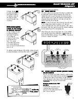
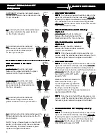
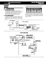
3. Ignition Lock Connection

Ignition Lock Connection

Ignition Lock Connection

Ignition Lock Connection

Ignition Lock Connection
In order for the circuit board to perform certain
functions, it must receive a signal when the vehicle
engine is running. This signal wire (16 gauge mini-
mum) should originate at the run terminal of the
ignition switch and connect to the "IGN lock" position
on the refrigerator terminal block.

7.2

7.2

7.2

7.2

7.2

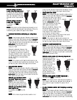
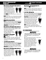
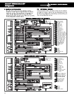
INTERNAL WIRING

INTERNAL WIRING

INTERNAL WIRING

INTERNAL WIRING

INTERNAL WIRING

Check all wires at the connectors to be sure of a proper
and tight connection. Also verify the refrigerator is wired
per the wiring diagram for the model you are working on.
(See wiring diagrams below).

A

7

B

7

C

7

D

7

E

7

F

7

G

7

GREEN

BLUE

YELLOW

ORANGE

BLACK
BROWN
RED

12V+
12V+

12V+

12V+

A

A

6

B

6

C

6

D

6

E

6

F

6

D

D

A 10
B 10
C 10
D 10
E 10
F 10
G 10
H 10
I

10

K 10

A

4

B

4

C

4

D

4

D

A
B

C
D

A 2
B 2

GRAY
BLACK

D

WHITE

BLACK

BLACK
BROWN
RED
ORANGE

B

BLACK
BROWN
RED
ORANGE
GREEN
YELLOW

BLACK
BROWN
RED
ORANGE
YELLOW
GREEN
BLUE
VIOLET
GRAY
WHITE

BLACK

ORANGE
BROWN

YELLOW

4

K

+

PL

L

D

RED
OR-

ANGE

YEL-

LOW

GREEN
BLUE

D

C

2

1

3

BLACK

120VOLTS AC

I

D

D

D

D

D

D

BLACK
BROWN

D

B

I

+

12 VOLT DC

IGN. LOCK

R

S

T

V

X

Y

M

A

OFF POSITION

+

E

J

I

I

4

C 120V AC

W

P

Q

H

X

G

F

CIRCUIT BOARD
TERMINAL BLOCK
HEATER
CONNECTOR
MAIN SWITCH
DOOR SWITCH
LIGHT
THERMOSTAT
GAS VALVE COIL
THERMOCOUPLE
REIGNITER
TIME FUSE 3–3.15 AMP
GAS FLAME WARN.

LAMP

GAS FUNCTION SWITCH
GAS FUNCTION LAMP
AES FUNCTION SWITCH
AES FUNCTION LAMP
120V AC MODE LAMP

DELAY MODE LAMP
ABSORPTION UNIT
GAS MODE LAMP
MODE SWITCH

WHITE
BLACK
GREEN
GREEN/YELLOW

A

B

C

D

E

F

G

H

I

J

K

L

Q

R

S

T

M

P

W

X

V

Y

1

2

3

4

GREEN

BLUE

YELLOW

ORANGE

BLACK
BROWN
RED

12V+
12V+

12V+

12V+

A

6

B

6

C

6

D

6

E

6

F

6

D

D

A 10
B 10
C 10
D 10
E 10
F 10
G 10
H 10
I

10

K 10

A

4

B

4

C

4

D

4

D

A
B

C
D

A 2
B 2

GRAY
BLACK

D

WHITE

BLACK

BLACK
BROWN
RED
ORANGE

B

BLACK
BROWN
RED
ORANGE
GREEN
YELLOW

BLACK
BROWN
RED
ORANGE
YELLOW
GREEN
BLUE
VIOLET
GRAY
WHITE

BLACK

ORANGE
BROWN

4

K

+

PL

D

RED
OR-

ANGE

YEL-

LOW

GREEN
BLUE

D

C

2

1

3

BLACK

120VOLTS AC

I

D

D

D

D

D

D

+

12 VOLT DC

IGN. LOCK

R

S

T

V

Y

M

A

OFF POSITION

+

E

J

I

I

4

W

H

X

G

F

A

7

B

7

C

7

D

7

E

7

F

7

G

7

A

P

U

X

I

B

2

5

1

L

Z

85

86

30

87

YELLOW

RED

D

BLACK
BROWN

N

O

Q

C

C

12V AC

120V AC

1

CIRCUIT BOARD
TERMINAL BLOCK
HEATER
CONNECTOR
MAIN SWITCH
DOOR SWITCH
LIGHT
THERMOSTAT
GAS VALVE COIL
THERMOCOUPLE
REIGNITER
TIME FUSE 3–3.15 AMP
GAS FLAME WARN. LAMP
AC/GAS FUNCTION SWITCH
AC/GAS FUNCTION LAMP
GAS FUNCTION SWITCH
GAS FUNCTION LAMP
AES FUNCTION SWITCH
AES FUNCTION LAMP
120V AC MODE LAMP
12V DC MODE LAMP
DELAY MODE LAMP
ABSORPTION UNIT
GAS MODE LAMP
MODE SWITCH
RELAY

WHITE
BLACK
GREEN
GREEN/YELLOW
BROWN

A

C

D

E

F

G

H

I

J

K

L

Q

R

S

T

P

W

X

V

Y

1

2

3

4

B

M

N

O

U

Z

5

RM3604 & RM3804 3-WAY 12/120 VOLTS

RM3604 & RM3804 3-WAY 12/120 VOLTS

RM3604 & RM3804 3-WAY 12/120 VOLTS

RM3604 & RM3804 3-WAY 12/120 VOLTS

RM3604 & RM3804 3-WAY 12/120 VOLTS

RM3604 & RM3804 2-WAY 120 VOLTS

RM3604 & RM3804 2-WAY 120 VOLTS

RM3604 & RM3804 2-WAY 120 VOLTS

RM3604 & RM3804 2-WAY 120 VOLTS
RM3604 & RM3804 2-WAY 120 VOLTS
Содержание RM3604

Страница 1: ...Foreword Foreword This service manual is the result of the dedication of The Dometic Corporation and its engineers in giving service people the necessary instruction for making accurate analyses of c...

Страница 2: ...it Board Switch Card 4 1 1 Fuse 9 SECTION 5 LP GAS REQUIREMENTS _ _ 10 SECTION 6 LP GAS COMPONENTS 6 1 Manual Shut Off Valve _ _ _ _ 10 6 2 Orifice 10 6 3 Thermocouple ___ _ _ __ __ _ _ 10 6 4 Burner...

Страница 3: ...Upper Circuit Board 4 9 2 12 Circuit Board 4 10 5 AC Volts 1 Heating Element 2 Upper Circuit Board 4 9 2 5 Wiring 7 2 Thermostat 4 2 Circuit Board 4 10 2 DC Volts 3 1 Heating Element 4 1 Upper Circuit...

Страница 4: ...14 Flame failure light after 3 minutes 15 Interior Light ON when door is closed 16 Rapid formation of frost AC Volts 1 Heating Element 2 DC Volts 3 Heating Element 4 1 Wiring 7 2 LP gas 5 1 Orifice 6...

Страница 5: ...Maximum fuse size 25 amp for RM3604 and RM3804 3 PRONG PLUG FOR 120V AC FUSE LINK 3AMP MANUAL GAS SHUTOFF VALVE IGN LOCK COVER TERMINAL BLOCK With the refrigerator operating on AC or gas mode if volta...

Страница 6: ...With the igniter producing spark connect meter leads to L and ground terminals on the igniter with the meter set on 20 volts DC range or lower The meter should read a pulsating voltage If not replace...

Страница 7: ...ld be off When the refrigerator door is open the switch is closed interior light should be on Check that the switch assembly is properly aligned and that it is not broken Check the switch assembly for...

Страница 8: ...turned to ON With the AES function switch manually With the AES function switch manually With the AES function switch manually With the AES function switch manually With the AES function switch manual...

Страница 9: ...ion switch With the gas function switch With the gas function switch With the gas function switch With the gas function switch NOT depressed NOT depressed NOT depressed NOT depressed NOT depressed A r...

Страница 10: ...amp and Switch NOTE The following checks should be made on the upper circuit board and harness assembly BEFORE replacing the upper circuit board or wiring harness The checks are to be done with the wi...

Страница 11: ...from meter If no voltage is present replace the circuit board If voltage is present the circuit board is NOT defective do not replace BLACK 6 Pin RED 6 Pin 4 THESE PROCEDURES MUST BE FOLLOWED IN SEQUE...

Страница 12: ...for a few moments while depressing the safety valve Remove the flame and release the safety valve The valve should hold for at least 30 seconds If it does not hold the safety valve open for 30 second...

Страница 13: ...te capacity to avoid voltage drop The wire gauge should be chosen with consideration to the wire length in accordance with the Table below MAXIMUM CONDUCTOR WIRE LENGTH IN FEET MAXIMUM CONDUCTOR WIRE...

Страница 14: ...F CIRCUIT BOARD TERMINALBLOCK HEATER CONNECTOR MAIN SWITCH DOOR SWITCH LIGHT THERMOSTAT GAS VALVE COIL THERMOCOUPLE REIGNITER TIME FUSE 3 3 15 AMP GAS FLAME WARN LAMP GAS FUNCTION SWITCH GAS FUNCTION...

Страница 15: ...eve proper air flow All potential dead air pockets should be blocked or baffled to insure that heat won t be trapped in these spaces and reduce efficiency In addition the cooling unit should be at lea...

Страница 16: ...tainers of water Next supply 115 volts direct to the AC heating element and operate for at least 12 hours Then check the temperature on the thermometer It should be at 45 degrees or lower depending on...

Отзывы: