8
SECTION C. OPERATING INSTRUCTIONS
1. IMPORTANCE OF LEVELING A REFRIGERATOR
In an absorption refrigerator system, ammonia is liquefied in
the finned condenser coil at the top of the refrigerator. The
liquid ammonia then flows into the evaporator (inside the
freezer section) and is exposed to a circulating flow of
hydrogen gas, which causes the ammonia to evaporate,
creating a cold condition in the freezer.
The tubing in the evaporator section is specifically sloped to
provide a continuous movement of liquid ammonia down-
ward by gravity through this section. If the refrigerator is
operated when it is not level and the vehicle is not moving,
liquid ammonia will accumulate in sections of the evaporator
tubing. This will slow the circulation of hydrogen and ammo-
nia gas, or in severe cases, completely block it, resulting in
a loss of cooling.
Any time the vehicle is parked for several hours with the
refrigerator operating, the vehicle should be leveled to
prevent this loss of cooling. The vehicle needs to be leveled
only so it is comfortable to live in (no noticeable sloping of
floors or walls).
When the vehicle is moving, the leveling is not critical as the
rolling and pitching motion of the vehicle will pass to either
side of level, keeping the liquid ammonia from accumulating
in the evaporator tubing.
2.
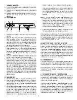
CONTROL PANEL
ON
OFF
AUTO
AC
GAS
1
2
CHECK COLD 1 2 3 4 5 COLDEST
3
A
D
D
C
B
E
F
2-WAY DISPLAY PANEL
3-WAY DISPLAY PANEL
LEGEND 2-WAY AMES MODEL
1. Main Power Button ON/OFF
2. AUTO/GAS Mode Selector Button
3. Temperature Selector Button
B. AC Mode Indicator Lamp
C. GAS Mode Indicator Lamp
D. AUTO Mode Indicator Lamp
E. CHECK Indicator Lamp
(GAS Mode Only)
F. Temperature Indicator Lamps
G. Climate Control Switch
(Drawing shows both switch locations)
LEGEND 3-WAY AMES MODEL
1. Main Power Button ON/OFF
2. DC Mode Selector Button
3. AUTO\GAS Mode Selector Button
4. Temperature Selector Button
A. DC Mode Indicator Lamp
B. AC Mode Indicator Lamp
C. GAS Mode Indicator Lamp
D. AUTO Mode Indicator Lamp
E. CHECK Indicator Lamp
(GAS Mode Only)
F. Temperature Indicator Lamps
G. Climate Control Switch
(Drawing shows both switch locations)
ON
OFF
AUTO
AC
GAS
1
CHECK COLD 1 2 3 4 5 COLDEST
4
2
3
F
E
C
B
G
G
FIG. 10

